New Pm 727m Mill

So,. lets see if I've got this right. You put the magnetic base on a solid, non-moving part of the column (like behind the dovetail, on the side. Then you set the indicator plunger on the side of the head, and run the head up and down, to see if the needle moves. If it shows movement, what would you adjust, to make it right ? Thanks, JR49
This would only indicate the head isn't square. And there is no way you'll get a head that is cast within a tolerance used for alignment :). You can, however, chuck a precision shaft in a collet and run this up and down. Note: most of the the "precision shaft" from McMaster-Carr is diametrically accurate, but it not suitable for this since it is warped over the length.

Here's a good video for this process:

 
That video that Tim (compsurge) posted is exactly what I did for my head to column alignment. I rechecked my spindle to table and was actually way off. I ended up sweeping the table with an indicator mounted in the quill to do the final adjustments for the column to table alignment, knowing that the head to column was as close to perfect as I could get it. However, the column to table was off approx. .018". I am not sure why I thought it was closer that that originally. In order to keep track of my shimming adjustments for the column, I just used a sharpie marker and noted the measurements at various locations on the table. I was swinging the indicator in a circle approx. 6" diameter, which put it about a 1/2" from each edge of the table (front and back). Then I kept shimming as I got it closer and closer. Once I was done, I verified with test cuts from large diameter end mills as well as my fly cutter.

It did take more shimming that I had imagined. I actually shimmed the left side of the column approx .120" which I thought was excessive, until I did more reading over the weekend. I found a couple of threads where people were talking about significant shimming along that same magnitude, for comparable square column machines. The interesting part was that when I got the machine out of the crate, the head to table tram was pretty good and it cut well initially. However, I noticed that the pointer for the head tilt was off approx. 1 full degree. After the head to column alignment, the pointer is now dead on the "0" mark. One other observation that I made was that when I put a level on my table, it is level in both directions. Before I got the column shimmed, I put the level on the dovetails and the bubble was off. Now, if I put a level on the dovetails, it is all level. Of course, this only works if the table is level.

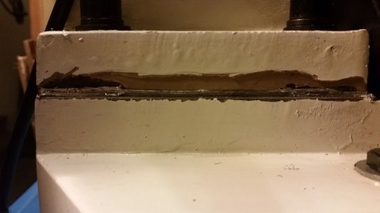
I have attached a picture of the shimming. There was a good amount of body filler used on this machine, some of which chipped off when I removed the column. When I got my 1127VF-lb lathe earlier this year, I did receive two small touch up paint cans, which I have never used on the lathe. I do plan to at least paint over the discolored parts to make it look a little better.

Sorry I haven't posted more pictures. I am still very happy with this machine. I would definitely recommend this machine for the home shop machinist. This is the perfect blend of rigidity and mass combined with smaller size and maneuverability. I am looking forward to getting my Igaging DRO's installed and then cranking out some accurate parts.

20150907_215136.jpg
 
Hoss does take half of the vid to actually get to the meat of the subject, but he left a couple of things out.

One, he didn't describe how/where to shim in the case of misalignment in Y, so I guess you just hope for the best? Or maybe the intent was to just show how to measure and the rest is up to you.

And two, he trammed the head with it being loose i.e., gibb locks not tightened down. When you lock the head to the column, the alignment will move. How much is dependent upon how well you have the gibb adjusted in the head mount but basically the head is cocked on the column ways because of it's weight and gravity and it will move when tightened down. Now I think he has converted that particular mill to cnc so he of course won't be locking the head, but folks using this mill manually might.

If you lock the head like I do before cutting, it might help to tram the same way.
 
A big thanks to 3dshooter, compsurge, and wrmiller19. I think I understand the process of checking the spindle (head) to column tram, and the column to table tram now. However, here is my confusion. On the square column mill, the head (spindle) is mounted to, (and slides on) the column with mating dovetails. So, if the spindle axis is not aligned (trammed) with the column axis, in X and Y, what and where do you make adjustments ?? I would have thought that this should be made perfect during manufacture, or like on a lathe cross slide, if travel isn't perfectly perpendicular to spindle axis, the only fix is re-scraping the dovetails. I'm sure I must be missing something. Please enlighten me, thanks again, JR49
 
As long as the head moves parallel to the column, There are a few places to make adjustment. The tilt of the head would affect the X-tram of the head to the table (rotate the head). Any Y tilt will likely be the column base squareness to the table (shim the column). A head nod (head not in tram with the column) could be a gibs tightness or the parallelism of the dovetail/ways to head mating surface. Make sure the shaft you are using is straight.

Even tightening the head bolts will make variations in the ~0.001" scale. See if working the bolts helps fix any nod. My running theory is to find anything loose and fiddle with it to see how it affects the dial indicator. If the machine can move on the ways and the gibs are tightened sufficiently to remove any "slack" that could be made by hand movement of the cast iron components.

Are you able to take a video or photo of the measurements in question as well as show your setup? Hopefully, that will allow us to see any issues you might have as well.
 
Congratulations!! Looking forward to your review with a great amount of interest!!
 
JR49, your assumption is correct that these things "should" be manufactured perfectly square, but the reality is, they typically aren't perfect. What you have to understand initially are what the constants are and what is adjustable. The constants are the travel of the head up and down the column via the dovetail ways, and the travel of the table front and rear (Y axis) and left to right (X axis). Those are the things we cannot change. What we can change / adjust are the alignment of the head / spindle along the X axis by means of loosening the bolts and rotating the head, the "nod" of the head (possibly by shimming between the head and the carriage assembly, but I wouldn't recommend that unless absolutely necessary since the shims could slide out of place when the head is roatated. Also, the nod would be off if the head was rotated anyways as the shim location would be dependent on the rotational position of the had in relation to the head carriage), and the other thing we can adjust is the column alignment by means of shimming between the column mounting flanges and the base itself. Like compsurge stated, the relative tightness or looseness of the gibs will affect the alignment of the head as well. When the gibs are tightened, it pulls the head into tight alignment with the dovetail ways. When they are loosened, gravity wants to pull the head down and away from the column.

Anytime we check alignment, the gibs must be tight. In a perfect scenario, I suppose you could get crazy technical and utilize a small torque wrench to insure that each time you lock down the gibs, the torque is identical. But, that is overkill for me. Now that we have assumed the gibs will be tight each time we make an adjustment, we focus on adjusting the head in the X axis. Just like in the video from Hoss machine that we posted already, we check the runout of a shaft with the head low and then raise it up and check it again. As long as the run out is centered over the "0" mark in both cases, the spindle is running true to the column travel. All you have to do is to see which way the run out is off and adjust the opposite way. I would suggest using one end as the "0" end and the other as the relative end to be measured. For me, I used the top of the shaft, close to the collet, as my "0" end. Then I raised the head up approx. 6" and measured the run out at the bottom of the shaft. Then you simply loosen the head bolts, rotate the head as needed (keep the indicator on the shaft and use this to guide your rotational efforts), and then lock the head back down. Then go back to your "0" end, reset your "0" as it will be off now, and then run the head back up and check the runout again. Keep in mind, each time you move the head, before you measure anything, you have to tighten the locking gibs down to insure the head is in tight alignment with the dovetail ways.

So, now we assume that the head has been aligned to the column. For me, I ended up putting an indicator in my spindle and held in place with a collet. Then I bring the indicator down to the table and zero it at the edge of the table closest to me. The as you rotate the spindle, you can observe and record the readings. Most likely, you will have a high reading on one side and a low reading on the other side. Then you loosen you column and shim between the column flange and the base to get the whole column and head to tilt towards the side of the table with the low readings. This is where you would do any tweaking to the Y axis in addition to the X axis. Once you get the indicator reading "0" all the way around the table, call it good, grab a cold beer, and pat yourself on the back.

Then, make some friggin chips!!
 
Wow, what a great explanation, 3dshooter,and compsurge. I got it now, and hopefully, will remember it because, to answer compsurge's request for pics and info, I don't presently have a mill. I will be getting one (probably the 727m, with 3dshooter's recommendation) in a few months once my health issues are resolved. I hope Matt still has them in stock when I'm ready. Looking forward to seeing more pics and updates on that 727m, 3d, thanks, JR49
 
I must have missed who I was replying to @JR49! Hope your health improves. Once you get the mill, you'll find it's a lot simpler than it may sound over the internet. Let us know if you get a 727 or step up to the 940 (or creep up to a 935)!
 
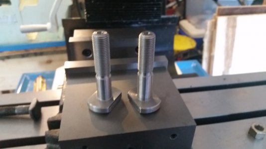
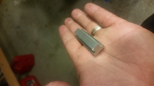
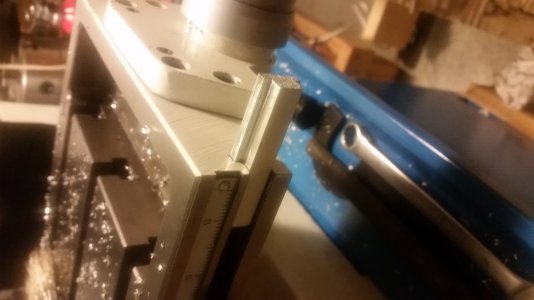
Well, I got some new t bolts made up for my vise and got it all squared up tonight. Once I had that all set, I started on a couple of nice new t nuts that will attach my igaging dro to the slot along the front of the table. It is only fitting that the first part I made on the new mill was for the new mill. I intend to use my X2 mill to fab up the rest of the parts, because I don't really like milling without dro's! I'll keep everybody posted with my progress.

20150910_175727.jpg 20150910_200819.jpg 20150910_200848.jpg
 
Back
Top