- Joined
- Aug 30, 2023
- Messages
- 4
I've got a new Grizzly G4003G Lathe and I wanted a simple two axis DRO. I found a lot of good write-ups online and in the forum, but not many that were recent, so I wanted to share my experience for future travelers looking for options. I have a lot of experience with CNC and mills, but I am a complete beginner with the lathe (my son is far more advanced) and my needs are purely garage hobbyist -- we make parts for large liquid rockets.
In my set up I wanted a DRO for the carriage travel and the cross slide, but I didn't need it for the tailstock (I am adding a digital caliper to the tailstock). So, I only need a basic two axis model.
DRO SELECTION
I did a lot of research on the different types of DROs and the different types of scales. Honestly, I wasn't really impressed with any of them. A DRO consists of the head unit and an optical or magnetic scale. The head units have a broad range of features and functions, screen types, and mounts, but most of the LCD/display units are cheap and churned out from China in bulk. The magnetic scales were interesting, but my experience with magnetic tape in other situations concerned me, so I went with the "cheap and reliable" optical glass linear scales. The glass scales come in three sizes - large/standard (KA300 25mmx25mm), medium (KA500 18mmx20mm), and very small (KA200 16mmx16mm).
I didn't really have a budget in mind, but I wanted to spend less than $1000. That said, I also didn't feel like over paying, so I went dirt cheap for my first DRO, knowing I could always upgrade parts or the whole thing later. I purchased the "ToAuto" 2 Axis DRO from Amazon (link below) w/200mm and 950mm sliders for $228. It comes with the large KA300 linear scales. The large scales are fine for the carriage, but for the cross-slide I wanted something smaller and more compact, so I "splurged" on a KA500 220mm linear scale from AliExpress -- all in with shipping it was only $69. So, the total spend for the DRO was $297.
ORDERING
After I ordered the ToAuto DRO from Amazon I got contacted by the seller to confirm the size I needed. The way they measure is super confusing, but ultimately I determined I needed a 950 and a 200, although I did not end up using the 200. There are multiple ways to measure scales, so be careful when you order. The ToAuto shipment arrived within 10 days.
The order from AliExpress was easy and arrived in California before the ToAuto order -- about 8 days.
PRE-INSTALLATION
After I got both packages, I hooked up the linear slides to the head unit and then powered it on to test it out on the bench. I realized that the smaller KA500 slide I ordered from AliExpress wasn't compatible, even though it had a standard DB9 connector. I went online and found the wiring for both the ToAuto and the YHSINO KA500 unit and I realized the KA500 was wired wrong. In fairness to the AliExpress seller, they had a note on the product page encouraging buyers to contact them and provide the type of DRO being used so they could wire it properly. Regardless, it was a pretty easy fix for me, because I do a lot of soldering. I opened up the DB9 connector on the KA500 slider and changed the wiring to the following: pin 1 red, 2 black, 3 green, 4 orange, white wire unused (free). After soldering the new pinouts the KA500 worked perfect.
On the bench and on the lathe I get about 2/10,000" sensitivity with both sensors. Both are rated at 5um, so good as advertised.
CROSS SLIDE INSTALLATION (YHSINO KA500)
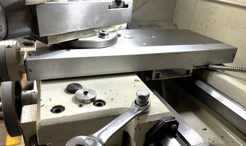
You can mount the sensor and the slide on the right or left side of the saddle, but if you mount it on the left side then you lose the mount point for the Follow Rest on the saddle. So I mounted it on the right (tail) side of the cross slide. I was hoping I could just drill and tap directly to the side of the cross slide, but there is a gib screw on each end of the cross slide that prevents you from drilling into the sides. Instead, I drilled and tapped a 4mm hole from the top (see photos) and fabricated a simple straight bracket to the linear slide ends. My brackets aren't a perfect 90 degrees, because I snapped off a 4mm tap in one end (metric garbage tap) and had to drill a second hole. It still mounted perfect.
The sensor for the slide mounts right below the cross slide on the saddle between the ways. It is threaded with 4mm threads. I tapped two 4mm holes and it mounted perfect without any additional spacer or bracket. I added a metal cable-tie to the back of the saddle to hold the sensor cable in place. Overall, the cross slide was an easy install, although it did need two simple custom brackets.
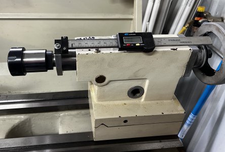
CARRIAGE INSTALLATION (ToAuto KA300 slide)
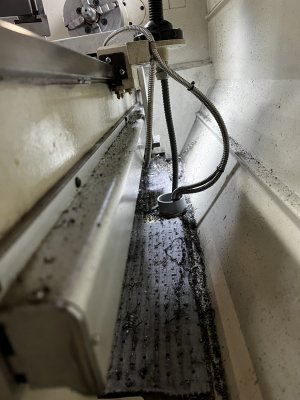
For the carriage linear slide install I removed the splash guard to make more room. I mounted the slide to the back of the bed "(yellow) facing up" and the sensor connected to a bracket that attaches to the back of the saddle. For the bracket, I cut down four inches of the bracket that ToAuto supplied. I mounted the sensor using four 4mm screws (supplied) and then I drilled/tapped two 5mm holes to hold the bracket to the saddle. I found that the bracket just barely scraped along the back of the bed, so I shimmed it with 3mm of washers.
For the long optical slide, I drilled/tapped a 5mm hole at each end. I found I needed to shim it with 4mm of washers off the bed back to align it perfectly with the sensor. I also added a metal wire clip to hold the sensor wire tight against the moving saddle. Overall, the carriage slide was just as easy as the cross slide, but required slightly modifying one of the supplied brackets for the sensor.
Note I did not use any of the other brackets or covers or clips supplied in the kit. I did consider mounting the long carriage slider "facing down" (yellow seal is facing up), but that would have required a much more complex bracket fabrication. I am somewhat concerned that chips or shavings will get inside the sensor from the top. If that happens someday in the future I'll buy another cheap linear scale and fabricate it facing down.
DRO HEAD UNIT INSTALLATION
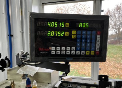
The head unit comes with an arm and a set of brackets. For the G4003G I found that mounting it directly on top of the power box was a good position for me, so all I needed to do was drill a 10mm hole in the power box and use a 10mm bolt (not supplied) to attach it. I also added two metal cable clips to the arm to better secure the sensor cables. The only issue with the positioning is that the DRO display is in line with the chuck and will likely get hit with oil, chips, etc.
IN SUMMARY
Overall, I am really happy with the choice and the install. Ask me in six months and I might have a different opinion. I am getting 2/10000" on both axis and full range end to end. The full install only took an afternoon on Saturday and a morning on Sunday, so I have no complaints.
Here are links to what I bought and photos of the install...
Amazon - ToAuto DRO (ordered 200x950 but didn't use the 200)
AliExpress - YHSINO KA500 220mm
Cross slide install


Carriage linear slide Install from behind


Head Unit Install


Final finished product (yep, she is in a tight corner)


Bonus - Manual TOC

In my set up I wanted a DRO for the carriage travel and the cross slide, but I didn't need it for the tailstock (I am adding a digital caliper to the tailstock). So, I only need a basic two axis model.
DRO SELECTION
I did a lot of research on the different types of DROs and the different types of scales. Honestly, I wasn't really impressed with any of them. A DRO consists of the head unit and an optical or magnetic scale. The head units have a broad range of features and functions, screen types, and mounts, but most of the LCD/display units are cheap and churned out from China in bulk. The magnetic scales were interesting, but my experience with magnetic tape in other situations concerned me, so I went with the "cheap and reliable" optical glass linear scales. The glass scales come in three sizes - large/standard (KA300 25mmx25mm), medium (KA500 18mmx20mm), and very small (KA200 16mmx16mm).
I didn't really have a budget in mind, but I wanted to spend less than $1000. That said, I also didn't feel like over paying, so I went dirt cheap for my first DRO, knowing I could always upgrade parts or the whole thing later. I purchased the "ToAuto" 2 Axis DRO from Amazon (link below) w/200mm and 950mm sliders for $228. It comes with the large KA300 linear scales. The large scales are fine for the carriage, but for the cross-slide I wanted something smaller and more compact, so I "splurged" on a KA500 220mm linear scale from AliExpress -- all in with shipping it was only $69. So, the total spend for the DRO was $297.
ORDERING
After I ordered the ToAuto DRO from Amazon I got contacted by the seller to confirm the size I needed. The way they measure is super confusing, but ultimately I determined I needed a 950 and a 200, although I did not end up using the 200. There are multiple ways to measure scales, so be careful when you order. The ToAuto shipment arrived within 10 days.
The order from AliExpress was easy and arrived in California before the ToAuto order -- about 8 days.
PRE-INSTALLATION
After I got both packages, I hooked up the linear slides to the head unit and then powered it on to test it out on the bench. I realized that the smaller KA500 slide I ordered from AliExpress wasn't compatible, even though it had a standard DB9 connector. I went online and found the wiring for both the ToAuto and the YHSINO KA500 unit and I realized the KA500 was wired wrong. In fairness to the AliExpress seller, they had a note on the product page encouraging buyers to contact them and provide the type of DRO being used so they could wire it properly. Regardless, it was a pretty easy fix for me, because I do a lot of soldering. I opened up the DB9 connector on the KA500 slider and changed the wiring to the following: pin 1 red, 2 black, 3 green, 4 orange, white wire unused (free). After soldering the new pinouts the KA500 worked perfect.
On the bench and on the lathe I get about 2/10,000" sensitivity with both sensors. Both are rated at 5um, so good as advertised.
CROSS SLIDE INSTALLATION (YHSINO KA500)
You can mount the sensor and the slide on the right or left side of the saddle, but if you mount it on the left side then you lose the mount point for the Follow Rest on the saddle. So I mounted it on the right (tail) side of the cross slide. I was hoping I could just drill and tap directly to the side of the cross slide, but there is a gib screw on each end of the cross slide that prevents you from drilling into the sides. Instead, I drilled and tapped a 4mm hole from the top (see photos) and fabricated a simple straight bracket to the linear slide ends. My brackets aren't a perfect 90 degrees, because I snapped off a 4mm tap in one end (metric garbage tap) and had to drill a second hole. It still mounted perfect.
The sensor for the slide mounts right below the cross slide on the saddle between the ways. It is threaded with 4mm threads. I tapped two 4mm holes and it mounted perfect without any additional spacer or bracket. I added a metal cable-tie to the back of the saddle to hold the sensor cable in place. Overall, the cross slide was an easy install, although it did need two simple custom brackets.
CARRIAGE INSTALLATION (ToAuto KA300 slide)
For the carriage linear slide install I removed the splash guard to make more room. I mounted the slide to the back of the bed "(yellow) facing up" and the sensor connected to a bracket that attaches to the back of the saddle. For the bracket, I cut down four inches of the bracket that ToAuto supplied. I mounted the sensor using four 4mm screws (supplied) and then I drilled/tapped two 5mm holes to hold the bracket to the saddle. I found that the bracket just barely scraped along the back of the bed, so I shimmed it with 3mm of washers.
For the long optical slide, I drilled/tapped a 5mm hole at each end. I found I needed to shim it with 4mm of washers off the bed back to align it perfectly with the sensor. I also added a metal wire clip to hold the sensor wire tight against the moving saddle. Overall, the carriage slide was just as easy as the cross slide, but required slightly modifying one of the supplied brackets for the sensor.
Note I did not use any of the other brackets or covers or clips supplied in the kit. I did consider mounting the long carriage slider "facing down" (yellow seal is facing up), but that would have required a much more complex bracket fabrication. I am somewhat concerned that chips or shavings will get inside the sensor from the top. If that happens someday in the future I'll buy another cheap linear scale and fabricate it facing down.
DRO HEAD UNIT INSTALLATION
The head unit comes with an arm and a set of brackets. For the G4003G I found that mounting it directly on top of the power box was a good position for me, so all I needed to do was drill a 10mm hole in the power box and use a 10mm bolt (not supplied) to attach it. I also added two metal cable clips to the arm to better secure the sensor cables. The only issue with the positioning is that the DRO display is in line with the chuck and will likely get hit with oil, chips, etc.
IN SUMMARY
Overall, I am really happy with the choice and the install. Ask me in six months and I might have a different opinion. I am getting 2/10000" on both axis and full range end to end. The full install only took an afternoon on Saturday and a morning on Sunday, so I have no complaints.
Here are links to what I bought and photos of the install...
Amazon - ToAuto DRO (ordered 200x950 but didn't use the 200)
AliExpress - YHSINO KA500 220mm
Cross slide install
Carriage linear slide Install from behind
Head Unit Install
Final finished product (yep, she is in a tight corner)
Bonus - Manual TOC