Need Wiring Connection Help

speedre9

Active User
Registered
Joined
Aug 26, 2013
Messages
167
Got my controller board, yes it's Chinese, but I need some help. I can understand where to connect the motors and the spindle and the main power but, I don't know where to connect the e stop button, or the limits and home switches, when I'm ready to add them in on my system. HELP! I'm starting the wiring today. Image of board added. I know I must be crazy!!
 

Attachments

  • IRAFORM3.pdf
    2.9 MB · Views: 15
Last edited by a moderator:
The parallel port has 5 input lines, pins; 10, 11, 12, 13, 15. You need to use a common limit switch for each of the axis inputs (Home, +Limit, -Limit), so for X-axis you would connect the limit switch to IN1 (pin 10 in Mach3), if you have 3 separate limit switches for those functions, then you would need to wire them in series. The E-Stop could be connected to IN4 or IN5. IN4 is probably pin 13 in Mach3, the default for the E-stop.

It looks like there are also some other inputs that are accessible by using the GPIO (20 pin) connector. You would have to find a cable and breakout connector for that.

Cable http://www.digikey.com/product-detail/en/M3AAA-2020K/M3AAA-2020K-ND/474

Breakout http://www.digikey.com/product-detail/en/2315049/277-2264-ND/1982808

I assume you have the manual for the board, if not, here is the link.

http://www.omc-stepperonline.com/download/pdf/3_Axis_TB6600_CNC_Driver_Board_Users_Manual.pdf
 
Last edited:
to add to what jim has said, in the manual it shows pin numbers and their uses. look at pins 10,11,12,13,15 they are labeled in1 thru in5 on your board.
and you have 5v or a ground there available so you can use input hi or low in the setup in mach3

3-Axis TB6600 CNC Driver Board Users Manual
3
sales@stepperonline.com www.omc-stepperonline.com
PIN Pin Symbols Description
1 PWM 0-10V output control
2 STEPX X axis pulse
3 DIRX X axis direction
4 STEPY Y axis pulse
5 DIRY Y axis direction
6 STEPZ Z axis pulse
7 DIRZ Z axis direction
8 STEPA Extending axis pulse
9 DIRA/Reply 1 Extending axis direction/Relay 1 control
(If control relay 1, please linking-up the jumper)
10 LIMIT-1 LPT input signal 1
11 LIMIT-2 LPT input signal 2
12 LIMIT-3 LPT input signal 3
13 LIMIT-4 LPT input signal 4
14 ENABLE_ALL All axis enable input
15 LIMIT-5 LPT input signal 5
16 RELAY2 Relay 2 control
17 RELAY3 Relay 3 control
5V 5V Power for MCU (+5V)
GND GND GND


steve
 
The parallel port has 5 input lines, pins; 10, 11, 12, 13, 15. You need to use a common limit switch for each of the axis inputs (Home, +Limit, -Limit), so for X-axis you would connect the limit switch to IN1 (pin 10 in Mach3), if you have 3 separate limit switches for those functions, then you would need to wire them in series. The E-Stop could be connected to IN4 or IN5. IN4 is probably pin 13 in Mach3, the default for the E-stop.

It looks like there are also some other inputs that are accessible by using the GPIO (20 pin) connector. You would have to find a cable and breakout connector for that.

Cable http://www.digikey.com/product-detail/en/M3AAA-2020K/M3AAA-2020K-ND/474

Breakout http://www.digikey.com/product-detail/en/2315049/277-2264-ND/1982808

I assume you have the manual for the board, if not, here is the link.

http://www.omc-stepperonline.com/download/pdf/3_Axis_TB6600_CNC_Driver_Board_Users_Manual.pdf

I get the e stop connection but I don't understand the limit switch connection. If I use a limit switch for each end of travel, say x plus and x negative travel, they would connect to IN1, and the same for Y axis, but to IN2 ,and IN 3 for Z axis travel. Is that correct? And because I'm not sure how is series wired?
 
I get the e stop connection but I don't understand the limit switch connection. If I use a limit switch for each end of travel, say x plus and x negative travel, they would connect to IN1, and the same for Y axis, but to IN2 ,and IN 3 for Z axis travel. Is that correct? And because I'm not sure how is series wired?

That is correct, X to IN1, Y to IN2, Z to IN3

The diagram below shows 2 switches in series. This particular diagram shows a battery, a light bulb, and 2 switches. Both switches must be closed for the light bulb to turn on.

1.png

Normally when using Mach3, I use only one limit switch for each axis. It performs all 3 functions, Home, and +/- Limit.

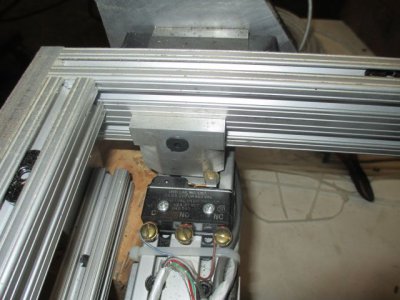
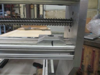
Here is a picture of the Y axis limit on a machine I'm working on right now.
IMG_0435.jpg

And this is the cam profile

IMG_0436.jpg

I have one of these cams for each end of the travel on both the X and Y axis. You would have to modify the cams a bit to fit your Z axis.

IMG_0435.jpg IMG_0436.jpg

1.png

1.png

1.png
 
Last edited:
here is a pdf of the mach3 installation guide that I found helpful
section 4.6 goes into good detail about different methods of wiring
if short on pins you can use 1 pin for all six limit switches wired in series
mach3 knows what switch opened because it knows the direction it is sending the axis.
steve
 

Attachments

  • Mach3Mill_1.84.pdf
    5.6 MB · Views: 10
Back
Top