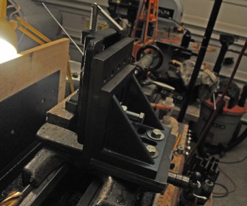
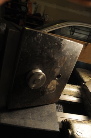
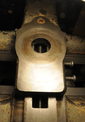
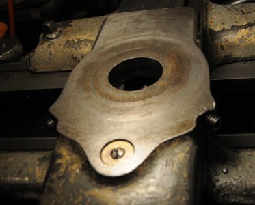
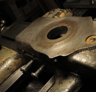
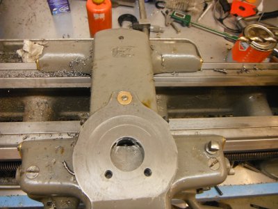
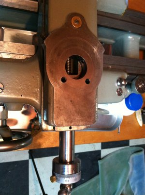
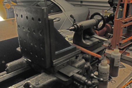
Here’s my latest mill attachment for my South Bend 9A lathe. My first one was exactly like this but made using wood, as a mockup (it actually worked on wood and soft metal).</SPAN>
My intent is to make do with this until a decent mill can be afforded, rather than buy or make a pricey mill attachment that is half the cost of a real mill. Since I’ll be furlowed soon by Uncle Sam, it may be a long time before I can afford a nice Bridgeport Mill.</SPAN>
Original plan was to make the face plate T-slotted, but just decided would be quicker to do it this way. Actually got lazy to be honest.</SPAN>
Bottom plate and side plate are ¾” hot rolled. Since I don’t have a bandsaw, I cut them on my table saw with a 10” fibre cutoff wheel. I hit both sides so ended up with a ridge in the middle where it didn’t line up. The table saw can actually cut steel faster than a bandsaw and the wheels are just 3 bucks.</SPAN>
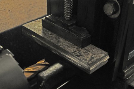
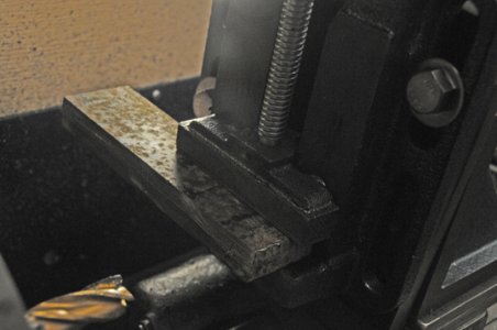
The scrap steel in the pictures is from carving up the plate, and I tested a ¾” end mill on it to clean up the edge using climbing cuts and non-climbing cuts. Feed depth was .005 and cuts were interrupted.</SPAN>
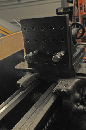
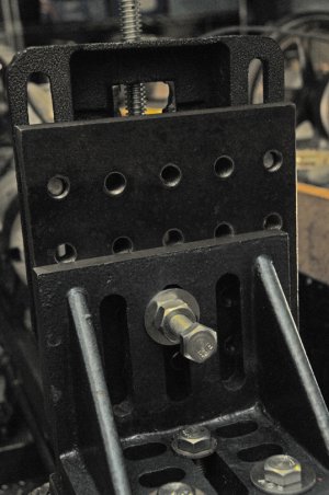
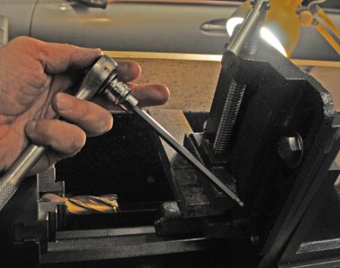
All 20 holes on the side plate and all 3 holes (including the one holding the 60 degree taper button that fits into the crossslide, are 1/2X13, drilled out with a 29/64 bit that is 135 angle and tapped. The tapping was hard so I used an old fashioned handle from a car scissor jack to assist. Tap was backed in and out and cool tool lubricant. My biggest fear was breaking the tap, but it held, as it is American made.</SPAN>
The side plate is 7” X 7”, and the angle plate is 6” X 6”. Angle plate got off Amazon for $20 not including shipping. The steel for the side and bottom plates was $20 from a metal dealer in Elk Ridge MD. The button (not photo’d) was turned from CR1018 1.75” diameter, from nearby BMG metal shop in Manassas VA. I purchased 12 feet of it so I have several buttons, a test bar and a lot left to play around with.</SPAN>
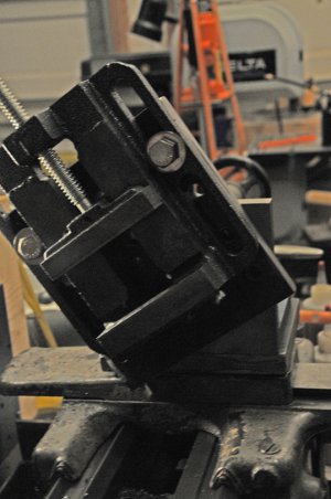
Oh, and the vise is 4” and was $20 from TSC.</SPAN>
The advantage of having all bolts the same ½-13 is that they all can be adjusted with my ¾” box wrench</SPAN>
The vise could be held by 4 bolts but I found that 2 suffice.</SPAN>
The side plate is held to the angle plate by just one bolt (1/2-13 of course). I was pleasantly surprised that it held so well. And what’s cool about using just one bolt is you can tilt it 360 degrees (the mill attachment can also be swiveled 360 degrees on the crossslide).</SPAN>
I don’t have any collets or end mill holders so I wrap each end mill in one layer of brown paper and chuck it. My biggest fear was the end mill would spin off, as I’ve had drill bits spin in my tail stock chuck. Again, I was pleasantly surprised b/c the cuts you take on this sort of fixture will never be deep so there’s less trauma there.</SPAN>
My first test was disappointing somewhat. It went thru wood and soft metal like butter but steel gave it problems. Specifically, it forced the entire attachment to spin around on the button that is attaching it to the crossslide. The force was so strong, it completely loosened the set screws that hold the button in the crosslide.</SPAN>
So I rechecked the button angle and it was 60 degrees and measured exactly like my compound button.</SPAN>
This would have been a show stopper for steel. I’d been using a hex key to tighten the set screws so I just got back from Lowes with a 3/8” socket hex for the 3/16 hex. This did 2 things. Since South Bend 9A made in 1942 put the set screws in the back of the crossslide, the extended reach of the hex drive made the miserable task of reaching around back under the mill attachment so, so , so much easier. Secondly, the ball hex wrench (in photo), allowed me to tighten the hex even more and this stopped the spinning of the mill attachment.</SPAN>
Once everything was secured, my 2[SUP]nd</SPAN>[/SUP] attempt actually worked and the steel was milled. Milling on a lathe is a pretty violent thing. Despite everything, you could see the thing groaning and nearly vibrating. I also locked down the carriage and unlocked and locked it with each pass.</SPAN>
Had one hand on the feed and the other on the off switch (I should make a foot kill switch). One improvement I may make would be to prop a block of wood under the attachment and resting on the ways like I’ve seen in pictures in popular mechanics. But with light cuts on steel and deep cuts on wood and soft metal, that’s not a must have.</SPAN>
So right away, you notice in the photos that there’s a problem with the Z axis as I did not build a screw to move it up and down. However, the vise can actually be moved way down and way up and down even below the crossslide using the holes on the side plate which line up with the 2 slots on the vise.</SPAN>
The Y axis is probably the most limiting aspect as you only get 6” of travel via the crosslide. The remedy is to simply turn the work around if it is really long.</SPAN>
The X axis is actually more advantageous than every mill except for the biggest ones, according to some experts, due to the greater length of a lathe. My lathe has a 42” bed (actually around 23 or so inches of real length).</SPAN>
My next project will be researching work-holding devices or simply playing around and making some myself with scraps of steel.</SPAN>
The mill attachment will mostly be used for making hobby train parts for my 1:13.7 scale trains I build. If you're every near Manassas VA stop by and you can see the mill and other things
daveV</SPAN>


