- Joined
- Apr 14, 2015
- Messages
- 43
Back when I was just finishing up machine tool in Vo-Tech (1975), they had just received a NC Bridgeport to start training the next year students. I dropped in a couple of years later to see the Bridgeport in action and wanted a CNC mill since. Back then you had to manually write the G code to a machine that then punched a bunch of holes into a paper tape. The paper tape was then put on a NC part of the Bridgeport to run the machine. How the world has changed since those days. Anyway, I never found a job in the machinist field and I ended up driving a trucks for the last 30 years, and over the road in a team operation the last 12. I had always wanted a mill and a lathe and I got my first small armature lathe in 1990. In 1998 I bought a HF round column mill-drill and installed a DRO on it. A year later I bought my Bridgeport (with DRO) and a Clausing 14 X 48 lathe.
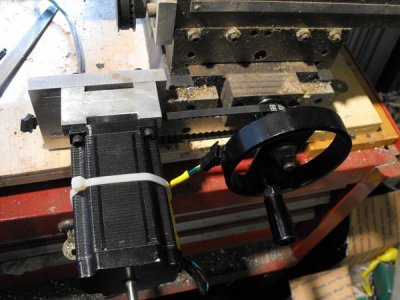
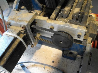
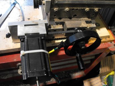
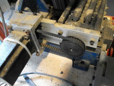
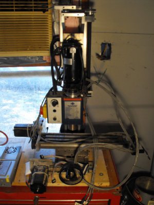
I was kinda late coming to the computer word and discovered the internet in about 2004 and found CNC zone. I made the plunge to convert a Cummings Tool 7877 mini mill (X2) to CNC. I bought the plans from fignoggle, the electronics from Xylotex, machined the all the mounts and ball screws. Also did the belt drive conversion on the spindle drive. Got it so the all the axis to turn with Mach 3. Now I had to start learning CAD and CAM. I tried a few and never could get anywhere with them and I gave up. Here is how the mill sits today.
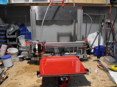
In 2012, I meet a guy that was forming a group to build some 3D printers and joined in with the thought that I would learn CAD and CAM. Got the printer, a Ord-Bot built and improved the design of the extruder we was using. I built about 25 of the Ord-Bot design printers and on the last 11, I increased the build to 300mm X 300mm X 300mm. As luck would have it, life got in the way, the group disbanded and I lost track of everybody, so I didn't get any help with CAD and CAM.
Here is one of the 300mm cubed printers.
I'm was to the point that I had to take some time to learn CAD. I discovered Shetchup 8 and watched a few youtube videos and I was drawing in no time at all. Now I can print everything I draw up. My son who is a computer nerd talked me into building a computer for working with 3D CAD programs. Now I have a computer with a I9 processor, solid state harddrive and very good processing graphics card.
This is where I'm at today.
OK now to the CAM part. I know my way around the slicing program (but when I updated it, I got lost and had to go back to the version I'm use to) I'm using. So now I need to learn a CAM that will work for the mill. A few years ago, I found a guy on craigslist that had a copy of Mastercam V9 for sale and he agreed to teach me how to use it if I bought it. Got it installed on my computer and he passed away a week later.
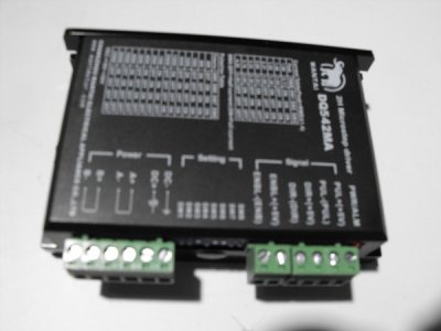
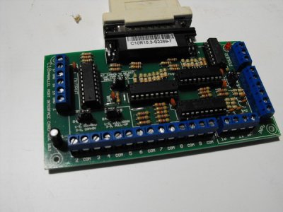
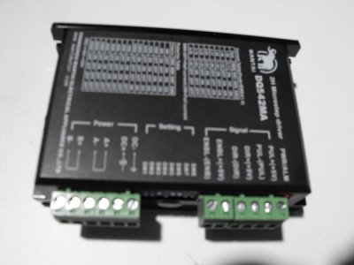
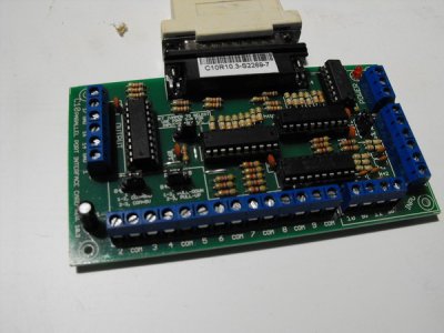
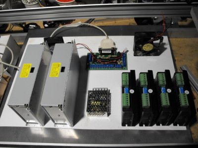
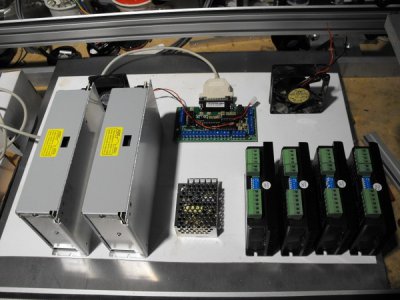
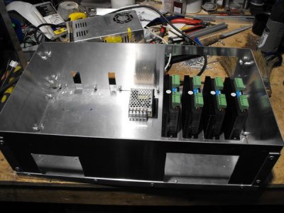
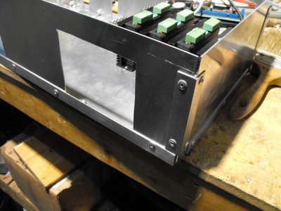
Being I have a hard time learning anything on the computer, I want to learn only one CAM program for now. I think I'm going with DeskProto being that they have a hobby version that supports the 4th and 5th axis. I found a few videos and I'll start looking at them tonight. But before I download the free trial, I want to update some of the stuff on the mill like the electronics and do away with the belt drive on the X and Y axis. I also need to build a good stand that will have a support for the column to keep it from moving.
Rodney
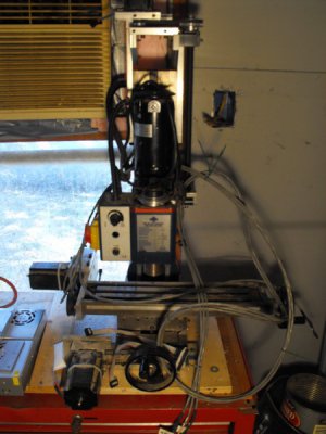
I was kinda late coming to the computer word and discovered the internet in about 2004 and found CNC zone. I made the plunge to convert a Cummings Tool 7877 mini mill (X2) to CNC. I bought the plans from fignoggle, the electronics from Xylotex, machined the all the mounts and ball screws. Also did the belt drive conversion on the spindle drive. Got it so the all the axis to turn with Mach 3. Now I had to start learning CAD and CAM. I tried a few and never could get anywhere with them and I gave up. Here is how the mill sits today.

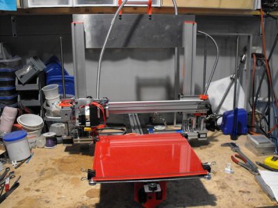
In 2012, I meet a guy that was forming a group to build some 3D printers and joined in with the thought that I would learn CAD and CAM. Got the printer, a Ord-Bot built and improved the design of the extruder we was using. I built about 25 of the Ord-Bot design printers and on the last 11, I increased the build to 300mm X 300mm X 300mm. As luck would have it, life got in the way, the group disbanded and I lost track of everybody, so I didn't get any help with CAD and CAM.
Here is one of the 300mm cubed printers.

I'm was to the point that I had to take some time to learn CAD. I discovered Shetchup 8 and watched a few youtube videos and I was drawing in no time at all. Now I can print everything I draw up. My son who is a computer nerd talked me into building a computer for working with 3D CAD programs. Now I have a computer with a I9 processor, solid state harddrive and very good processing graphics card.
This is where I'm at today.
OK now to the CAM part. I know my way around the slicing program (but when I updated it, I got lost and had to go back to the version I'm use to) I'm using. So now I need to learn a CAM that will work for the mill. A few years ago, I found a guy on craigslist that had a copy of Mastercam V9 for sale and he agreed to teach me how to use it if I bought it. Got it installed on my computer and he passed away a week later.
Being I have a hard time learning anything on the computer, I want to learn only one CAM program for now. I think I'm going with DeskProto being that they have a hobby version that supports the 4th and 5th axis. I found a few videos and I'll start looking at them tonight. But before I download the free trial, I want to update some of the stuff on the mill like the electronics and do away with the belt drive on the X and Y axis. I also need to build a good stand that will have a support for the column to keep it from moving.
Rodney


Last edited:


