- Joined
- Jun 17, 2011
- Messages
- 2,069
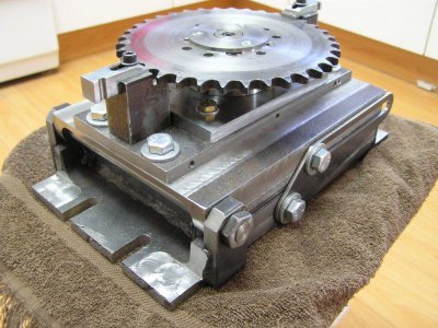
As requested, Here are the photos of the tilt table I made some time ago for my mini-mill. I'm trying a slightly smaller photo size this time. The base and top piece are cut from 6" channel iron.
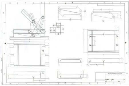
On some projects, I whip up a CAD drawing or two to remind me what I had in mind, and to work out critical dimensions.
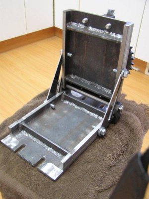
A view of the 'inside' of the table. After cutting the pieces to length, cross-braces should be welded in. Do this early, because welding will warp the piece and it can then be machined true.
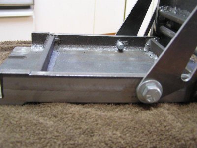
As the drawing shows, the sides of the channels are cut down to keep the total height of the table as low as possible. After I was nearly finished, I decided to thicken the ends of the base to provide clamping stiffness and clearance away from the bolts. Good idea to do that early as well.
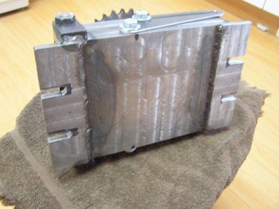
Clamp the base to the mill and true up the sides. Then mill down most of the sides a bit more, leaving pads at all four corners for the top to sit on when the table is level. Cut down the sides at the ends to leave the clamping flats. Repeat the process for the top section, ignoring the part about the clamping tabs. Round the bottom corner of the top piece at the pivot end.
Clamp the base section upside down to the mill table and true up the raised end sections. These should end up parallel to the four pads left on the sides of the base.
Weld on a pair of solid towers for the pivot bolt, which is made from 1/2" CRS, threaded 1/2" - 20. It is held by a couple of nuts made by cutting a 1/2" nut in half. The holes for the shaft need to be a really close fit.
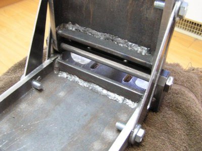
Spend some time with CAD or paper to get the dimensions right for the two clamping slides. The slot can be a bit longer than necessary for 0* and 90* positions. I used 3/8" bolts because I try to use only a few sizes of wrench around the shop for adjusting tool setups.
View attachment 247
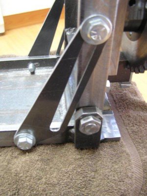
After the whole thing is assembled, bolt it down to the mill table, make sure the top is all the way down and clamped, and mill the top true. Then drill and tap any mounting holes you need.
This should give you enough info to design and build your own tilt table. The web on my channel iron was only 1/4" thick, so if you can get anything thicker, go for it.
Have fun in your shop.
Mike


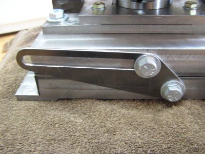

On some projects, I whip up a CAD drawing or two to remind me what I had in mind, and to work out critical dimensions.

A view of the 'inside' of the table. After cutting the pieces to length, cross-braces should be welded in. Do this early, because welding will warp the piece and it can then be machined true.

As the drawing shows, the sides of the channels are cut down to keep the total height of the table as low as possible. After I was nearly finished, I decided to thicken the ends of the base to provide clamping stiffness and clearance away from the bolts. Good idea to do that early as well.


Clamp the base to the mill and true up the sides. Then mill down most of the sides a bit more, leaving pads at all four corners for the top to sit on when the table is level. Cut down the sides at the ends to leave the clamping flats. Repeat the process for the top section, ignoring the part about the clamping tabs. Round the bottom corner of the top piece at the pivot end.
Clamp the base section upside down to the mill table and true up the raised end sections. These should end up parallel to the four pads left on the sides of the base.
Weld on a pair of solid towers for the pivot bolt, which is made from 1/2" CRS, threaded 1/2" - 20. It is held by a couple of nuts made by cutting a 1/2" nut in half. The holes for the shaft need to be a really close fit.

Spend some time with CAD or paper to get the dimensions right for the two clamping slides. The slot can be a bit longer than necessary for 0* and 90* positions. I used 3/8" bolts because I try to use only a few sizes of wrench around the shop for adjusting tool setups.
View attachment 247

After the whole thing is assembled, bolt it down to the mill table, make sure the top is all the way down and clamped, and mill the top true. Then drill and tap any mounting holes you need.
This should give you enough info to design and build your own tilt table. The web on my channel iron was only 1/4" thick, so if you can get anything thicker, go for it.
Have fun in your shop.
Mike


Last edited by a moderator:
