- Joined
- Feb 8, 2014
- Messages
- 11,176
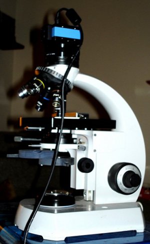
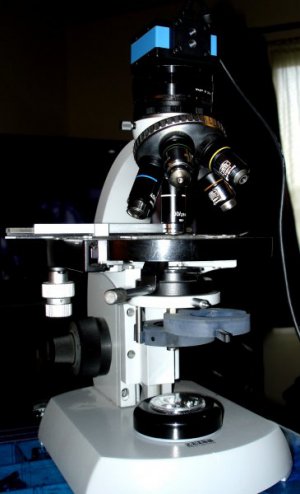
A couple of weeks ago I spent about 8 hours peering through a microscope to make some tooling to stamp out a very small electrical part. I got to thinking how nice it would be if I could display it on a screen rather than having the stare into the eyepiece. Yes, I know that there are microscope cameras available, but that was not an option at the time. That job was completed successfully and on the next project.
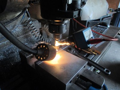
II had a few extra parts and pieces kicking around so I decided to make a camera mount for my spindle microscope. Not even sure how I’m going to use it just yet except that now I can ‘’look’’ through the microscope without twisting my neck around to get under the head.
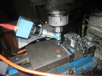
The only piece I had to make was the aluminum, slip on adapter. It doesn’t show in any of the pictures, but the sleeve is slotted so that it is a spring fit onto the microscope eyepiece. The lens end it threaded into the filter mount on the lens. A bit of a trick to figure out what the thread actually was. The only thing I had to work from was the internal threads of the lens. Pretty sure it’s 25mm x .75 but close enough to 32 TPI so I used that rather than change my lathe over to metric threads. I used the microscope to measure the thread pitch, then measured the minor diameter, and calculated the approximate major diameter. Then it was a matter of take a cut, check fit, file a little bit take another cut, rinse/repeat until the lens screws on.
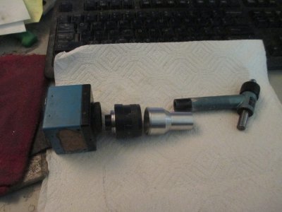
I found that one of the 16mm lenses that I had was the perfect focal length to work with the microscope. The camera is a color CCD, 640x480, industrial firewire camera. I use these cameras in some machine upgrades that I do for the lumber industry, used to measure board widths on the fly. The software will edge find and measure in 2 axis and will also measure in 3D if a laser is used as a light source.
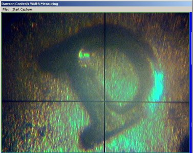
The microscope is 50x so it can see some pretty small features. I haven’t done the calibration yet, but the resolution should be a half thou or better. The cross hairs are from the retical in the microscope and are too wide on the screen. It removes easily and I’ll add a crosshair overlay on the picture. Once that is completed and calibrated, the crosshairs will line up properly on the machine axis, and will be centered on the spindle centerline. The software is capable of measuring features as a stand alone, or may be used with the DRO for measuring larger parts.
The lighting in this picture is terrible, from one side only. I need to build a tiny LED ring light for it. Also this scaled down picture does not do the actual image justice, it’s much clearer on the screen. The D in the picture is the mint mark on a penny.
The plan is to eventually automate the process for checking parts or something, but mostly just to play with.
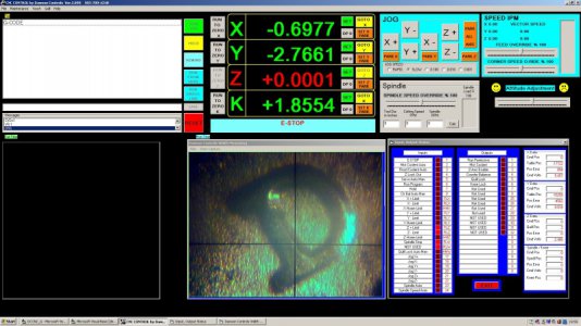
I integrated the imaging software into my CNC program, so all I have to do is bring up the picture with a mouse click. I wrote the imaging software a few years ago, so it was pretty much just drop the imaging modules into the CNC program, not a major programming effort.
II had a few extra parts and pieces kicking around so I decided to make a camera mount for my spindle microscope. Not even sure how I’m going to use it just yet except that now I can ‘’look’’ through the microscope without twisting my neck around to get under the head.

The only piece I had to make was the aluminum, slip on adapter. It doesn’t show in any of the pictures, but the sleeve is slotted so that it is a spring fit onto the microscope eyepiece. The lens end it threaded into the filter mount on the lens. A bit of a trick to figure out what the thread actually was. The only thing I had to work from was the internal threads of the lens. Pretty sure it’s 25mm x .75 but close enough to 32 TPI so I used that rather than change my lathe over to metric threads. I used the microscope to measure the thread pitch, then measured the minor diameter, and calculated the approximate major diameter. Then it was a matter of take a cut, check fit, file a little bit take another cut, rinse/repeat until the lens screws on.

I found that one of the 16mm lenses that I had was the perfect focal length to work with the microscope. The camera is a color CCD, 640x480, industrial firewire camera. I use these cameras in some machine upgrades that I do for the lumber industry, used to measure board widths on the fly. The software will edge find and measure in 2 axis and will also measure in 3D if a laser is used as a light source.
The microscope is 50x so it can see some pretty small features. I haven’t done the calibration yet, but the resolution should be a half thou or better. The cross hairs are from the retical in the microscope and are too wide on the screen. It removes easily and I’ll add a crosshair overlay on the picture. Once that is completed and calibrated, the crosshairs will line up properly on the machine axis, and will be centered on the spindle centerline. The software is capable of measuring features as a stand alone, or may be used with the DRO for measuring larger parts.
The lighting in this picture is terrible, from one side only. I need to build a tiny LED ring light for it. Also this scaled down picture does not do the actual image justice, it’s much clearer on the screen. The D in the picture is the mint mark on a penny.

The plan is to eventually automate the process for checking parts or something, but mostly just to play with.

I integrated the imaging software into my CNC program, so all I have to do is bring up the picture with a mouse click. I wrote the imaging software a few years ago, so it was pretty much just drop the imaging modules into the CNC program, not a major programming effort.

Last edited:

