Metric thread dial question...

o0norton0o

Registered
Registered
Joined
Dec 3, 2023
Messages
81
My metric lathe has a 2mm lead screw, and I am currently working on acquiring all the thread dial gears made for my lathe. They are 28, 36, and 40 tooth gears. I've been reading up on metric thread dial information and of course only now I see how much more complex a thread dial is on a metric lathe.

One of the informative explanations I read was that imperial threads are fractional because they are threads per inch, so they lend themselves to the fractional nature of the 360 degree dial marking system. But, metric threads are not fractional based thread sizes so they aren't as intuitive.... I don't completely understand this at a high enough level to understand all the implications.

I can see where having a 3mm lead screw would give you some crazy fractions to translate to a thread dial. I have a 2mm lead screw, and that seems like it could yield some workable fractions on a thread dial...

Is a 2mm lead screw and 28, 36, and 40 tooth thread dial gears always going to give me a thread dial with the 4 major compass points?? (N, S, E, W) My intuition tells me that I will be able to use the same dial with each gear, but I'm just guessing.

Anyone have a firm grip on metric thread dials and particularly the idea of a 2mm lead screw making a metric thread dial easier to understand?? thanks in advance
 
The fly in the ointment with metric thread dials is that they need the extra gears for fractional thread pitches (I think) They do not need seperate dials for the peculiar pitches, and some metric lathes have all 3 gears on the same shaft and are designed so that each grar can be grout into use without disturbing to other gears.
 
I found this on the internet about making a thread dial for a Boxford lathe with a metric lead screw. There are two parts to the build and the second part has info on the gears and the dial. Maybe you will find this useful.
 
The fly in the ointment with metric thread dials is that they need the extra gears for fractional thread pitches (I think) They do not need seperate dials for the peculiar pitches, and some metric lathes have all 3 gears on the same shaft and are designed so that each grar can be grout into use without disturbing to other gears.
Yes, I have seen those multigear dials. In some cases, that also means the dial on top has multiple sets of numbers. One set for each gear. I've seen one video where the guy makes 3 separate dial/shaft assemblies for each gear, so that he just inserts the proper dial and gear for the thread pitch he is cutting and the dial has the appropriate markings for that gear without having to remember which numbers to read. (so as to be less confusing, He made each gear has it's own designated dial) I am thinking about doing that as well. My problem is that I'm not yet up to speed on how those dial markings will differ. The fact that my lead screw pitch is the number "2" seems to me that it should lend itself to the simplest of all dials, being that 2 makes for simple math that results in a lot of whole numbers. I'm hoping someone who's already dealt with this will tell me that I'm ether on the right track, or "It doesn't work that way!".... :cool:

I found this on the internet about making a thread dial for a Boxford lathe with a metric lead screw. There are two parts to the build and the second part has info on the gears and the dial. Maybe you will find this useful.
I'll give that video a look. I bet I've already watched it because I've "googled" and "youtubed" the hell out of my metric thread dial project.


thank you guys for responding... I hate learning stuff! God only knows why I also feel compelled to learn :rolleyes:
 
When I look at an imperial thread dial it's symmetrical with numbers spaced evenly around the 360 degrees of the dial.

I understand how to make all the parts for the thread dial in the video. all very well done. I want an explanation of that asymmetry of that crazy dial and how you arrive at those intervals since they are not evenly divided..... Is it because his lead screw is 3mm. Will my thread dial be different because I have a 2mm lead screw?? (I would think yes)

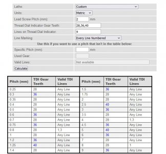
Here's a threading chart I created using an online calculator. I guess it assumes 4 symmetrical marks on my thread dial because of my 2mm lead screw... (It blows my mind to look at the lead screw in the video and no see symmetrical marks, then look at my own and see symmetrical marks.... I need to understand why..... I assume it's based on my lead screw pitch,... but I'm not sure... anyway here's my two images below.

One is the chart I created with all the chosen gears for each metric pitch, with the engagement numbers..thread dial gear chart1.jpg

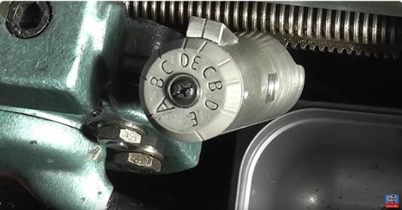
Here's the guy in the above video's thread dial.... Why isn't it symmetrical like mine?? (mine is marked with 4 equidistant marks)

3mm thread dial1.jpg

In his video he can start on "A" or "E".... So thinking logically, if the dial tracks the movement of the carriage, in order for the starting lines to repeat wouldn't the distance between A and E have to be the same as the distance back to A after passing E??? When I look at that dial there are 2 "E's" and A doesn't seem to be equidistant from them....

I think I have a lot of reading to do in the future to settle this in my head. I just want to better understand this before it shows up as mistakes on finished parts..... I am beginning to see why a lot of people call, leaving the half nuts engaged and backing up the lathe, "The European way of threading"
 
Back
Top