Metal bending questions

Maplehead

Registered
Registered
Joined
Feb 20, 2017
Messages
437
I am in search of some metal bending info.
Given my project in the two pics provided, I need to know how much tonnage for the press I will need to bend .0625", (16 gauge), steel plate.
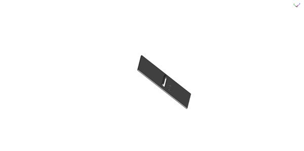
My project is unusual in that the bend is in the middle of the piece, but not encompassing bending the whole piece. See pics for what I mean.
My flange lengths are odd. They are .125" on the short side and just under 2" on the long side.
That adds difficulty in trying to figure this out.
Also, since I am not trying to bend the whole piece I must allow for one of the V die "lips" to be able to fit through the slot opening. This means the size of the lip is approximately 3/8".
The piece being bent out is .0625" thick by .125" high by approximately 2.5" long.
Given all of the above and the included pics, my questions are:
How many tons pressure to bend this small piece?
Can I use an arbor press to do so?
Should I get custom punch and die made? If so, anybody know a good place where to?
Should I just purchase angle iron and try to fashion punch and die myself? (I have a micro mill so not a ton of power and rigidity.)
Thanks for any and all advice and assistance.
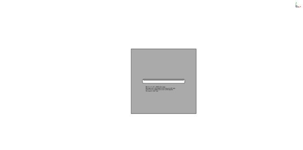
V bending slot side - front view.jpg

V bending slot side - angled view.jpg
 
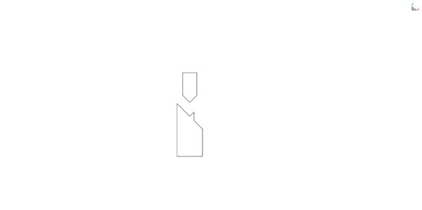
I'm thinking that the attached pic would be the profile for the punch and die. Thoughts?

Punch and Die with .060 nose radius.jpg
 
I have attached a tonnage chart. This could also be accomplished in one hit (shearing and forming) with a custom made lance die.
bb4b50bbca3f534eca51e3bdcab3ea81.jpg


Sent from my iPad using Tapatalk
 
I just figured it out so know need to reply. Now on to designing tonight.
 
You going to keep it a secret?

David
 
Didn't know there was interest.
This isn't a V die operation. It took me a while to realize that. Sprintcar's post triggered a thought.
First the pics I posted are just for this site. The real thing I am doing is not for public yet.
Anyways, what I will do is lay the plate onto a steel slab that holds the plate in place. I'll route out the plate's impression in the top of the steel slab to accomplish that.
Where the slot is I will route out a cavity in the steel slab. I will lay the plate onto the slab up-side-down.
Using a steel punch that has an end shaped like the cavity, but indented to account for the 1/16" lip, I will use the punch to push the lip down into the cavity.
It should end up at a right angle. Job accomplished.
I still don't know how much tonnage I will need for this.
I will make the punch and die and then try it on a vise first to get an idea of it's pressure requirements.
 
There are several ways to arrive at the finished product. If you are looking at mass produced then a punch and die with probably one or two hits on a punch press will do the trick. If this is a prototype then I would start with a punch and die brake setup that you can mill out along with milling the slot in the blank that you want to bend the flange on. The only requirement of course is the flange dimensions are less than the opening left in the flat plate I couldn't see enough detail in your photo's to determine the parameters so I was going off of your description. I bend metal every day and the tonnage is based on the material thickness, the length of the bend and the die that you are bending the material in. You could build yourself a small H-Frame press and use a small hydraulic jack but a quick try with the arbor press will probably work.

I see your die is angled and to what degree I can't tell nor why it needs to be angled. I can do the math but need clear dimensions. The opening in the plate is ?X?. Look at your die design again. The piece of metal being bent needs to be supported on both sides as the bending process begins. If the bend is 90° then your die dimension (centerline to the outside) on the outside of the die needs to be less than the opening in the plate. Without me drawing it out for you, allow the angle you have on the die to be an imaginary line that represents your plate. The top of the die is square and the vee can be cut into a 1" X 2.4375" X you pick a height" bar, off center to allow for the plate to bend down and clear the die. The vee width could be 3/8" max and from the center of the vee to the outside of the die (on one side) to allow the plate to clear the die. Draw the die with a 90° surface and then draw your plate in the position as it's formed. Billions of parts are formed every day with these configurations.

,ou can invest a lot of time and $$$ producing a punch and die (machined heat treated etc.) for a punch press operation, which can be laser cut and formed on a brake, but you can prototype this with a mill and imagination. -Russ

I'm thinking that the attached pic would be the profile for the punch and die. Thoughts?
The profile of the die would be the profile of your plate in the formed position. The opening in the plate would move downward as the solid side (opposite the opening) and flange move upward.
 
I'm thinking that the attached pic would be the profile for the punch and die. Thoughts?
That was a little verbose. :)

Looking at your die drawing profile/end view; Take the width of the vee as drawn and square the top of the die starting at the right side of the vee and move left. From the same starting point on the vee, draw a straight line vertically downward and remove all the material to the right. Mill a little more off the top of the vee to remove the sharp point of the vee on the right side, give it a .062" flat. Now you have a bottom die off-center to allow for the bend. If the tolerances are too close for this and the opening is too small, then drop down under the vee about 1/4" or more and take a half round cut along the die. If this were the upper punch we would call it a gooseneck which allows for bending a longer length than the width.

I have a 10" brake without a split bottom die so I do this when the need arises. I have to create a short bottom die that I drop into and secure to my 1" vee die. You can afix stops on your punch and die setup to allow for positioning your plate for repeatability. Bending parts that requires a section of the part to move downward in the bending process requires creativity.
 
Back
Top