- Joined
- Nov 17, 2013
- Messages
- 36
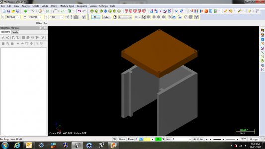
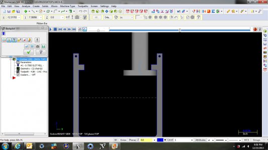
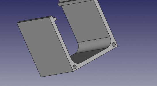
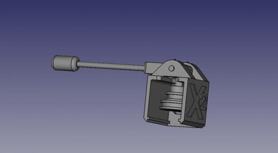
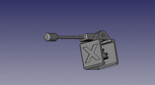
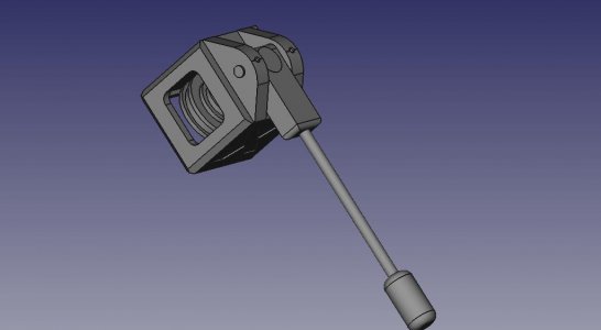
Below are pictures of a project that I have in mind. It is a manual power draw bar for the Sieg X2 mill. I have it rough cad'ed to get as far as the 3d rendering but I have questions on milling the body from one solid piece of aluminium. The block is mean to slide into a mating slot that will be machined into the new top plate of the belt drive system. I designed it this way so the upward forces would be transferred to the sides of the plate when the handle is actuated but it would still be easily removable for belt changes.
The part that eludes me is how do I mill the positive rail in the assembly but still be able to clean the corners where the rail meets the back of the front face?
Any suggestions would be greatly appreciated.
Things to note:
- Curved washers will be placed under the head of the draw bar (Hossmachine)
- At 13" the lever will need approximately 17 lbs of force applied to depress the washers. This may need to be longer to reduce the force needed as well as the added lateral force being placed on the head (my one huge concern).
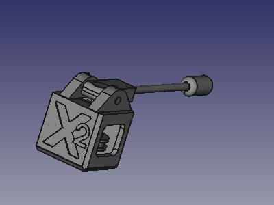
- The cam will more than likely have 2 lobes on it, one on the edge for pulling and releasing the actuator and one on the tip so you can place the handle in the vertical position, compressing the washers and holding them in the compressed position with out the need to hold the lever.


