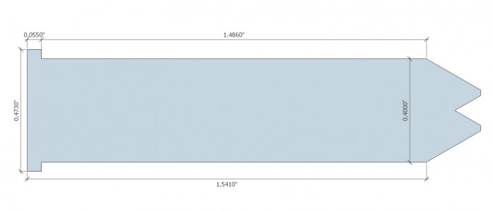
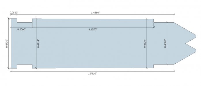
I just built my first AR308/DPMS pattern rifle in 6.5CM and was looking at Go/NoGo headspace gauges. At first glance they seemed simple enough to machine, until I realized the critical length references a diameter on the shoulder (.400" for 6.5CM according to SAAMI) and the tolerances are only a few thousandths between go and no go.
Looking through other gunsmithing forums, they all seem to advise just buying a set of gauges from a reputable source, which is understandable when you're dealing with explosives sitting a few inches from your face. However, this being a machinist forum, I was hoping I could at least start an academic discussion on the process.
From my amateurish understanding, the rough process would be to start with a piece of drill rod close to final diameter, turned down to the case max diameter (.473 for 6.5CM). Then turn a taper (30 degrees) to simulate the case shoulder. Then cut the part a little longer than final length.
Then to reference the shoulder datum (.400), you could drill, bore, and ream a bushing to exactly the datum diameter. Then face the bushing, mic the length, and keep that number as reference. Then the shoulder of the go/nogo gauge can be placed into the bushing and measured with a mic or calipers and further faced down to the final length (1.5438 -.0070).
The part I get hung up on is the right angle on the bushing between the face and .400 bore. Straight off the reamer, I imagine it could still have a bur on the edge, which could affect your measurement. But if you de-bur/chamfer the hole, you either change that critical .400 dimension, or the length of the bushing. I suppose you could lap the face of the bushing, and then the bore. That way any burs would be removed and the change to critical dimensions would be minimal.
Does that make sense? Am I missing something? Making it more complicated than it needs to be?


