- Joined
- Apr 5, 2011
- Messages
- 121
Hi guys
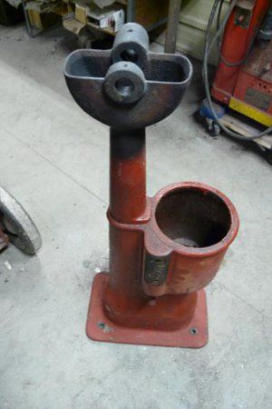
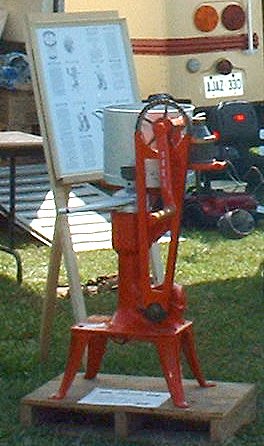
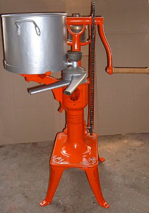
I am in the process of restoring a very rare 1908-10 International Harvester Bluebell cream separator. This machine had likely been sitting on some ones lawn for 50 years as a lawn ornament. No need to tell you what shape it was in, seized solid! It took about 20 years of soaking it and finally with the help of my welding torch I was able to get some movement in the crank. I played with it for about a week and finally got it apart.
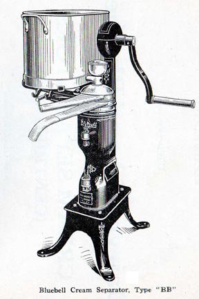
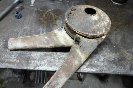
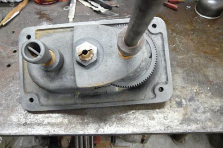
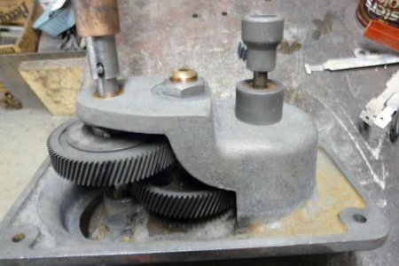
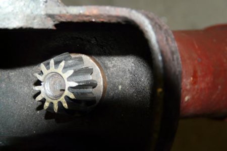
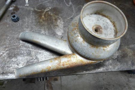
In the picture you see a small dome above the crank. In there is a large bevel crown gear attached to the crank shaft and a small 1 3/8" bevel pinion that drives a shaft going to the gear box in the bottom. That dome is a loose cover over those gears and it stood full of water for most of it's outdoor life. The result was that all the teeth on the pinion had rusted off except for the one engaged in the crown gear along with a half tooth on each side of it. The crown gear was cast and the pinion was steel. So I went on a quest to find a pinion or some one to make me one. I did contact Mike but he informed that he was not set up to be able to make one. Boson Gears could not match it either. So my good wife told me that I would just have to make one myself. Went to Machinery Hand Book and studied what it had to say. Years ago Home Shop Machinist also did a series on gear cutting. All of that information looked pretty daunting.
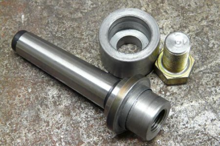
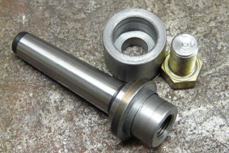
All I had to work with was my little Homier mill drill with the fine feed I built on it, a spin index, and an involute gear cutter that I was given when I bought my lathe. I Knew I could not make all the measurements that were required to cut a bevel gear but set out to give it a whirl with what I had anyway. First thing was to make an arbor for the cutter with a No 2 taper. I had bought several blank draw bar arbors from Busy Bee years ago. The taper was finished but the end was blank so proceeded to turn the end down to a shoulder about 1/8" wide where the taper started and about 7/8" diameter. I inserted the arbor into a sleeve in the headstock of my 9" SB. Then I turned a collar to fit over it with an interference fit. The cutter I had needed a 1" shaft and the end of the arbor was 1" so needed something to hold the cutter against. I heated the collar with the torch and dropped it over the shaft. Once cooled down I machined a step on it to hold the cutter. Then I machined a cup that was a close fit over the 7/8" stub and drilled it 9/16". Then I drilled the end of the stub for a 9/16" fine thread and tapped it. I was going for 1/2' but grabbed the wrong drill bit so now we have 9/16" NF in it. I chose NF because it is easier to get a good tight pressure to hold the cutter.
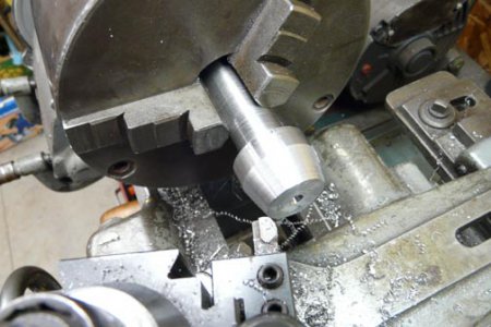
Next we went back to the lathe grabbed a piece of scrap shaft about 1 1/2" diameter. Turned a portion down to 7/8" diameter and then turned it end for end and finished the remaining stub to 1 3/8" The diameter I concluded the gear must have been from measuring from the top of the good tooth to the shaft and the doubling that. I had no protractor to measure the angle of the pinion to the shaft so just held the shaft with the bad gear on it against my tool post which I had squared as accurate as you can by eye to the compound. Loosened the compound and turned it until it looked right with the eye. I proceeded to cut the taper with the compound. When I got about 1/2 done I held the shaft with the one good tooth against my taper and sited down to the bed ways. I made some miner adjustment until it looked right to me and finished the taper.
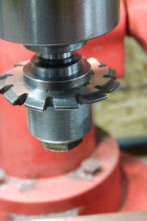
Next how to set it up in the mill? Years ago I had drilled two holes in the base of the spin index so I could hold it on my lathe table. I set the Y axis back as far as it could travel, Eyeball the alignment and height and proceeded to make a cut. That went surprisingly smooth so proceeded to cut the rest of the teeth. Since there were 12 teeth on this gear it was rather easy to divide. As luck would have it the cutter I had matched the tooth profile at the small end of the gear. I missed one space on the index and ruined one tooth but finished cutting them all to test it on the crown. It was close but the cut was too deep and the same depth front to back. Almost worked with some filing buy not good enough.
So since my Y travel was to the end I had elongate my holes in the base of the index to give me more room to play with. I turned it upside down in my mill vise and used the mill to do that. That is what happened to fancy paint job.
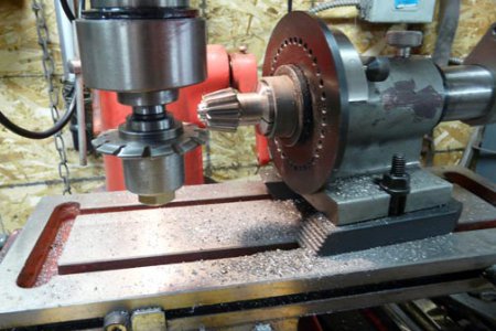
Now we had plenty of adjustment. Made a new blank on a 7/8" stem and cut the second blank. Mounted it in the mill and repeated the first operation. The first cut went in about 3 passes but went a bit too deep so backed it off a bit for the rest of the cuts. I also eye balled the angle a bit so that the small end would be shallower than the large end. The end result looked pretty good so filed the teeth some as we had a shoulder on the large end on the side at the top of the tooth. When satisfied that the fit on the crown seemed good we went back to the lathe and turned the 7/8" shaft to 5/8", the size of the original shaft and bushing where it had to ride in and cut of the bit that was held in the chuck.
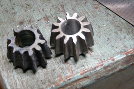
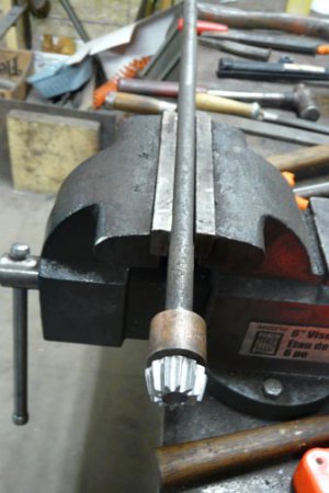
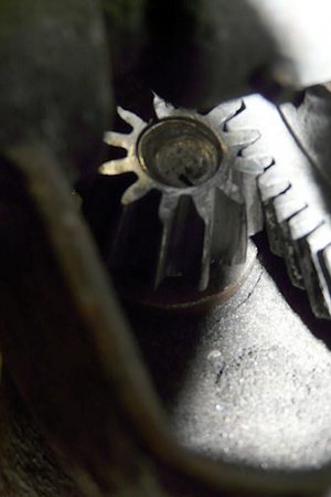
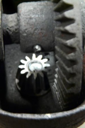
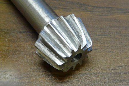
Dropped it into the bushing, slipped the crown gear into place, slipped the crank shaft in and locked the crown gear to the shaft. Gave the crank a turned. Felt a few tight spots but after several turns it was running smoothly. Not what I would call a gear suitable for high speed or a lot of pressure but it sure beats 1 tooth and two halves. So here is our finished gear. Not bad for a first time gear cut. Nick


I am in the process of restoring a very rare 1908-10 International Harvester Bluebell cream separator. This machine had likely been sitting on some ones lawn for 50 years as a lawn ornament. No need to tell you what shape it was in, seized solid! It took about 20 years of soaking it and finally with the help of my welding torch I was able to get some movement in the crank. I played with it for about a week and finally got it apart.

In the picture you see a small dome above the crank. In there is a large bevel crown gear attached to the crank shaft and a small 1 3/8" bevel pinion that drives a shaft going to the gear box in the bottom. That dome is a loose cover over those gears and it stood full of water for most of it's outdoor life. The result was that all the teeth on the pinion had rusted off except for the one engaged in the crown gear along with a half tooth on each side of it. The crown gear was cast and the pinion was steel. So I went on a quest to find a pinion or some one to make me one. I did contact Mike but he informed that he was not set up to be able to make one. Boson Gears could not match it either. So my good wife told me that I would just have to make one myself. Went to Machinery Hand Book and studied what it had to say. Years ago Home Shop Machinist also did a series on gear cutting. All of that information looked pretty daunting.
All I had to work with was my little Homier mill drill with the fine feed I built on it, a spin index, and an involute gear cutter that I was given when I bought my lathe. I Knew I could not make all the measurements that were required to cut a bevel gear but set out to give it a whirl with what I had anyway. First thing was to make an arbor for the cutter with a No 2 taper. I had bought several blank draw bar arbors from Busy Bee years ago. The taper was finished but the end was blank so proceeded to turn the end down to a shoulder about 1/8" wide where the taper started and about 7/8" diameter. I inserted the arbor into a sleeve in the headstock of my 9" SB. Then I turned a collar to fit over it with an interference fit. The cutter I had needed a 1" shaft and the end of the arbor was 1" so needed something to hold the cutter against. I heated the collar with the torch and dropped it over the shaft. Once cooled down I machined a step on it to hold the cutter. Then I machined a cup that was a close fit over the 7/8" stub and drilled it 9/16". Then I drilled the end of the stub for a 9/16" fine thread and tapped it. I was going for 1/2' but grabbed the wrong drill bit so now we have 9/16" NF in it. I chose NF because it is easier to get a good tight pressure to hold the cutter.


Next we went back to the lathe grabbed a piece of scrap shaft about 1 1/2" diameter. Turned a portion down to 7/8" diameter and then turned it end for end and finished the remaining stub to 1 3/8" The diameter I concluded the gear must have been from measuring from the top of the good tooth to the shaft and the doubling that. I had no protractor to measure the angle of the pinion to the shaft so just held the shaft with the bad gear on it against my tool post which I had squared as accurate as you can by eye to the compound. Loosened the compound and turned it until it looked right with the eye. I proceeded to cut the taper with the compound. When I got about 1/2 done I held the shaft with the one good tooth against my taper and sited down to the bed ways. I made some miner adjustment until it looked right to me and finished the taper.

Next how to set it up in the mill? Years ago I had drilled two holes in the base of the spin index so I could hold it on my lathe table. I set the Y axis back as far as it could travel, Eyeball the alignment and height and proceeded to make a cut. That went surprisingly smooth so proceeded to cut the rest of the teeth. Since there were 12 teeth on this gear it was rather easy to divide. As luck would have it the cutter I had matched the tooth profile at the small end of the gear. I missed one space on the index and ruined one tooth but finished cutting them all to test it on the crown. It was close but the cut was too deep and the same depth front to back. Almost worked with some filing buy not good enough.
So since my Y travel was to the end I had elongate my holes in the base of the index to give me more room to play with. I turned it upside down in my mill vise and used the mill to do that. That is what happened to fancy paint job.

Now we had plenty of adjustment. Made a new blank on a 7/8" stem and cut the second blank. Mounted it in the mill and repeated the first operation. The first cut went in about 3 passes but went a bit too deep so backed it off a bit for the rest of the cuts. I also eye balled the angle a bit so that the small end would be shallower than the large end. The end result looked pretty good so filed the teeth some as we had a shoulder on the large end on the side at the top of the tooth. When satisfied that the fit on the crown seemed good we went back to the lathe and turned the 7/8" shaft to 5/8", the size of the original shaft and bushing where it had to ride in and cut of the bit that was held in the chuck.
Dropped it into the bushing, slipped the crown gear into place, slipped the crank shaft in and locked the crown gear to the shaft. Gave the crank a turned. Felt a few tight spots but after several turns it was running smoothly. Not what I would call a gear suitable for high speed or a lot of pressure but it sure beats 1 tooth and two halves. So here is our finished gear. Not bad for a first time gear cut. Nick


Last edited:


