- Joined
- Apr 21, 2015
- Messages
- 653
As promised, herewith are my experiences thus far machining a replacement cross-slide casting from Andy Lofquist at Metal Lathe Accessories to fit my Logan/Wards 11" lathe.
As I described in another thread, I want to replace the rather short cross-slide that came with the lathe originally. I want to replace it with a much longer one with tee-slots in the rear (so that I can use a rear-mounted toolpost, rear-mounted boring bar holder, etc., without necessarily removing the compound slide). Unfortunately, the drawings that Andy made are for a South Bend lathe which uses a different attachment mechanism for the compound slide.
As described in the previous thread, the trickiest thing to wrap my head around before getting started was how to mill the circular tee slot. Please see that thread for details.
This is just the first of likely several posts in this thread.
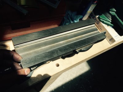
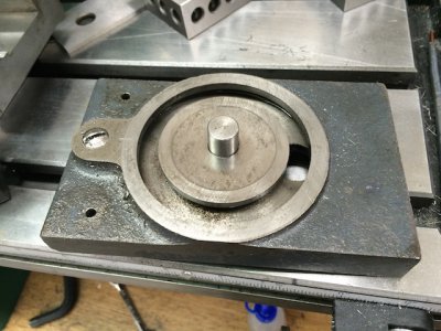
Here's a shot of the original cross-slide (with the guide nut installed):
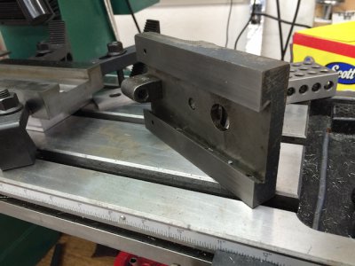
The first thing I did was to mill the bottom of the casting to use as a reference surface for all subsequent tasks. Unfortunately I didn't take any photos of this, but I just used a flycutter to flatten the "ways" on the bottom, then used an end-mill to clean up the center channel. I then used this bottom surface as a datum plane to mill the sides roughly square and the top roughly parallel.
At this point I discovered just how janky the cheap milling vice I purchased is — even with the quill of the mill trammed within a thou of the mill table, the vice itself was quite a bit out of tram (several thou). Sigh. Not a big deal at this point where I'm just rough milling. I'll deal with it later.
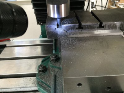
Next I milled the tee-slots in the rear:
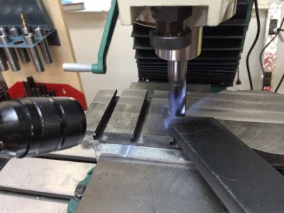
After getting things in better tram, I used my nice carbide end-mill to better clean up the top (notice the vacuum sucking up swarf — cast iron is messy messy messy and even with ways covered it tended to get everywhere):
Next I cleaned up the sides a bit more (bad practice having the clamp jacks over a slot like that — should have used pieces of scrap to span the gap):
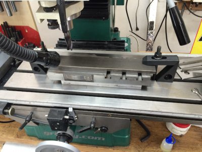
That carbide end-mill sure leaves a beautiful finish on the cast iron.
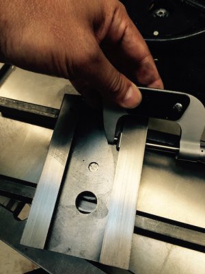
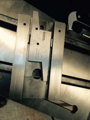
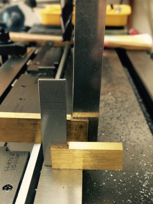
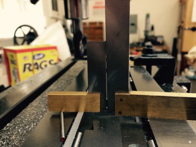
Now I was ready to start on the dovetail slot on the bottom. First I used some quarter-inch dowel pins and a micrometer to carefully measure everything on the original. Distance from the side to the bearing (non-gib) side of the dovetail, and distance between the dovetail sides. I also depth mic'ed the distance from the bottom bearing surface to the non-bearing parallel inside surface.
Once again I should have taken pictures of the measuring. I'll post some pics of the process tomorrow. The only remotely clever bit was using an adjustable parallel to measure the distance between the two dowel pins.
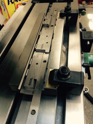
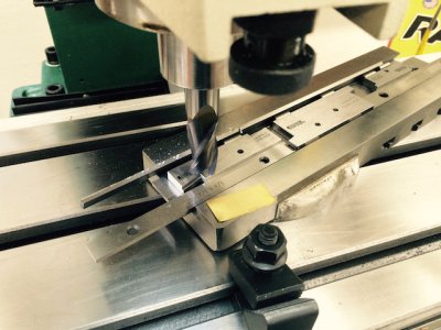
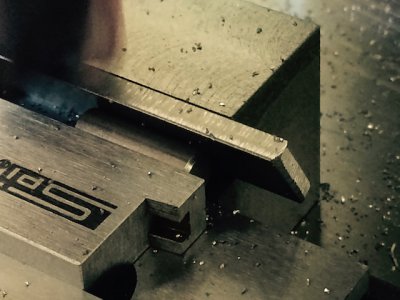
I used the straight carbide endmill to widen the slot roughly to size (to my great annoyance, I actually overshot a bit, but fortunately it was on the gib side). Then I got out the 60 degree dovetail cutter and went to work:
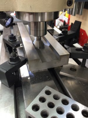
Because my workholding kind of sucked (I should have just clamped down on the top surfaces, but somehow convinced myself I didn't have room and needed clearance on top) I took very light cuts each pass.
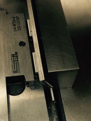
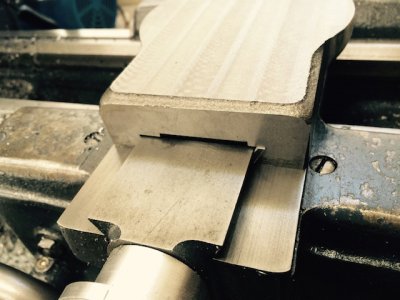
After I had both sides cut I just had to try it out, of course, to ensure I hadn't done anything wildly wrong to this point:
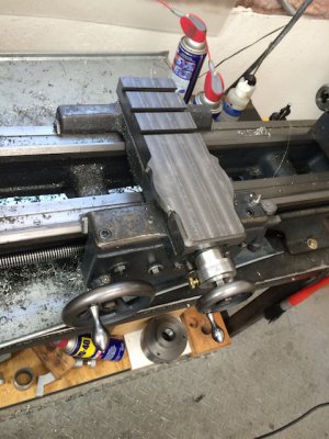
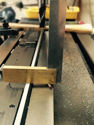
It fit great, and more importantly, it passed my very basic tests:
As I described in another thread, I want to replace the rather short cross-slide that came with the lathe originally. I want to replace it with a much longer one with tee-slots in the rear (so that I can use a rear-mounted toolpost, rear-mounted boring bar holder, etc., without necessarily removing the compound slide). Unfortunately, the drawings that Andy made are for a South Bend lathe which uses a different attachment mechanism for the compound slide.
As described in the previous thread, the trickiest thing to wrap my head around before getting started was how to mill the circular tee slot. Please see that thread for details.
This is just the first of likely several posts in this thread.
Here's a shot of the original cross-slide (with the guide nut installed):


The first thing I did was to mill the bottom of the casting to use as a reference surface for all subsequent tasks. Unfortunately I didn't take any photos of this, but I just used a flycutter to flatten the "ways" on the bottom, then used an end-mill to clean up the center channel. I then used this bottom surface as a datum plane to mill the sides roughly square and the top roughly parallel.
At this point I discovered just how janky the cheap milling vice I purchased is — even with the quill of the mill trammed within a thou of the mill table, the vice itself was quite a bit out of tram (several thou). Sigh. Not a big deal at this point where I'm just rough milling. I'll deal with it later.
Next I milled the tee-slots in the rear:

After getting things in better tram, I used my nice carbide end-mill to better clean up the top (notice the vacuum sucking up swarf — cast iron is messy messy messy and even with ways covered it tended to get everywhere):

Next I cleaned up the sides a bit more (bad practice having the clamp jacks over a slot like that — should have used pieces of scrap to span the gap):

That carbide end-mill sure leaves a beautiful finish on the cast iron.
Now I was ready to start on the dovetail slot on the bottom. First I used some quarter-inch dowel pins and a micrometer to carefully measure everything on the original. Distance from the side to the bearing (non-gib) side of the dovetail, and distance between the dovetail sides. I also depth mic'ed the distance from the bottom bearing surface to the non-bearing parallel inside surface.
Once again I should have taken pictures of the measuring. I'll post some pics of the process tomorrow. The only remotely clever bit was using an adjustable parallel to measure the distance between the two dowel pins.
I used the straight carbide endmill to widen the slot roughly to size (to my great annoyance, I actually overshot a bit, but fortunately it was on the gib side). Then I got out the 60 degree dovetail cutter and went to work:

Because my workholding kind of sucked (I should have just clamped down on the top surfaces, but somehow convinced myself I didn't have room and needed clearance on top) I took very light cuts each pass.
After I had both sides cut I just had to try it out, of course, to ensure I hadn't done anything wildly wrong to this point:

It fit great, and more importantly, it passed my very basic tests:
- I put a mag base dial indicator on top, and measured the deflection on a faceplate as I slide the top-slide for and aft (while pushing the whole top-slide to the right by hand to ensure it was bearing on the dovetail surface). Total deflection was just two or three tenths over about 5.5 inches.
- I took the short gib from the original and ensured that there was room to slide it in on the right side with very little room to play. (I haven't machined the new long gib yet, so it won't fit vertically.)
- Machining the angles on the short sides of the gib.
- Boring and tapping the holes in the right side for the gib screws.
- Boring and pressing a locating pin on the right side of the casting as well as a corresponding hole in the gib (to prevent it shifting fore and aft)
- Machining the circular tee-slot to attach the compound.
- Boring a press-fit hole for the center locating pin for the compound (and pressing in the 0.5" pin)
- Boring and tapping the workholding holes on the top of the slide
- Machining appropriate bits to attach the nut for the crossfeed screw.
- Final lapping and scraping of all bearing surfaces (something I've never attempted)
- Doubtless dozens of other things I'm forgetting (like painting — God I hate painting)
Last edited:

