Looking to make a friend in Northern Virginia with 3ph power

FliesLikeABrick

Wastestream salvage addict
H-M Lifetime Diamond Member
Joined
Oct 30, 2019
Messages
201
Hello,

I have a 3 ton chain hoist I have finished repairing and am looking to make a local friend with 3ph power that I can test it on. Due to the controls layout, a VFD is not sufficient to test this otherwise I would do it myself.

Anyone have a commercial or other space where I could borrow a 3-pole 15-20 amp breaker in your panel for 30 minutes? Would be happy to figure out what favors I might be able to offer in exchange at some point.

I have a local contact with a rotary phase converter but it is not quite healthy at the moment - it would be nice to test this on native 3ph to avoid chasing ghosts.
 
Even a simple static converter should be sufficient to test a motor, one can be made from a couple of capacitors, plenty of designs on the internet.
 
I had a bit of a crazy idea, and need someone to hear me out.

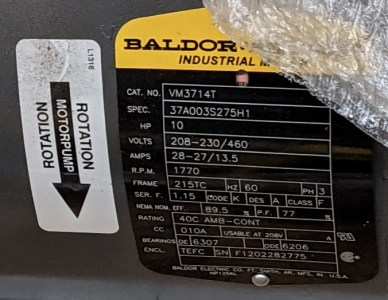
On the shelf I have two brand new 3ph motors that I got at an auction. I have been wondering what to do with them, haven't found anyone to buy them yet. They are a 10hp Baldor and a 7.5hp Baldor.

To test my relatively small hoist, I started wondering if I could just temporarily use one as a rotary phase converter. Instead of buying capacitors to regulate the voltage on the manufactured leg.... what if I ran the 10hp motor as a phase converter (using another motor to help it start); then ran the 7.5 hp motor off of it to help regulate the voltage.

Then my intermittent 1hp load for the chain hoist starting/stopping would be insignificant, and see stable voltages.

My concern about using capacitors to actually build a rotary phase converter isn't just the cost for a temporary need; it is also that my single-phase voltages at home tend to be in the 255-258vac range. This would put my manufactured phase even higher, like 275-285... and I'm just not thrilled about putting my newly-repaired chain hoist on that.

I am still researching phase converter builds so I may be missing something significant. Take comfort in the fact that I am not about to rush into this, but while brainstorming and researching this idea came to me so I am wondering if it technically sound at all.

1645746784650.png
 
Last edited:
Even a simple static converter should be sufficient to test a motor, one can be made from a couple of capacitors, plenty of designs on the internet.
That did come up in my options, however this would be an intermittent load -- starting and stopping as the pendant controls are pressed. I believe the commercial static phase converters automatically enable the 3rd leg when starting and disconnect when started... so I'm not sure how well I could use that with an intermittent load.

The intermittent nature is the same reason a VFD isn't great here. To use a VFD I would need to wire it directly to the motor and rewire the pendant control, limit switches, and other safeties to control the VFD via low-voltage inputs... and that just bypasses 50% of the repair that I am looking to validate
I see, yeah a VFD is not ideal but a properly working rotary or static should work fine.
I had a static setup on my South Bend Heavy 10 Lathe for years, I put it through thousands of instant, forward-reverse cycles, not letting it stop first, while tapping/threading. I had no issues other than it only delivering ⅔ hp. Now I have that lathe on a rotary converter and it still switches instantly between forward-reverse but at full power.
 
I see that you are sitting on 2 three phase motors!
I built my own Rotary Phase Converter, It's really not that difficult and the capacitors are not expensive. You could easily do a temporary set-up with one of those motors, but as far as I know, you need the capacitors. Regarding the high voltages you are reading, is your meter a true RMS type? Some meters aren't and will show higher voltages than what's actually doing the work. I also wouldn't worry about the manufactured leg being significantly higher, I got all the phases of my RPC to within about 5% of each other, 10% is considered acceptable.
Thanks, I will consider it. I may end up trying my 2-motor idea unless someone can tell me for certain that it won't work -- I think the risk is low, as long as I monitor voltages and currents; and do not let either motor stall. However yes, I will look into capacitors and if I can get those for cheap+fast enough, I will do so.

As for my friend's RPC setup - I need to measure again next time I am there. I recall being surprised to see voltages in the 260-280v ranges but I do not recall the exact voltages. They may very well be within 10% of each other, and if his single-phase from the street is 255-258 volts like mine is -- then 260-280v may not be unexpected.

Indeed I was using a true RMS meter, but thank you for pointing it out -- there is a chance that one of these times I am looking at it I would have otherwise ended up reaching for another meter.
 
I see that you are sitting on 2 three phase motors!
I built my own Rotary Phase Converter, It's really not that difficult and the capacitors are not expensive. You could easily do a temporary set-up with one of those motors, but as far as I know, you need the capacitors. Regarding the high voltages you are reading, is your meter a true RMS type? Some meters aren't and will show higher voltages than what's actually doing the work. I also wouldn't worry about the manufactured leg being significantly higher, I got all the phases of my RPC to within about 5% of each other, 10% is considered acceptable.
my cedarburg does not use capacitors. The legs are not balanced. The motor starts normally and generates a third leg.
 
my cedarburg does not use capacitors. The legs are not balanced. The motor starts normally and generates a third leg.

How does it work, do you have a schematic?
I am curious as I have researched the subject quite a bit and never saw a circuit that didn't use a capacitor.
I have a static converter (Phase-a-Matic) and basically all it is, is an aluminum box with a capacitor in it.

I found, the unbalanced phase converter circuit caused a lot of vibration in the idler motor, and humming-vibration in the driven motor as well. Thats what led me down my rabbit hole of building my own.
 
Back
Top