- Joined
- Dec 26, 2015
- Messages
- 2,139
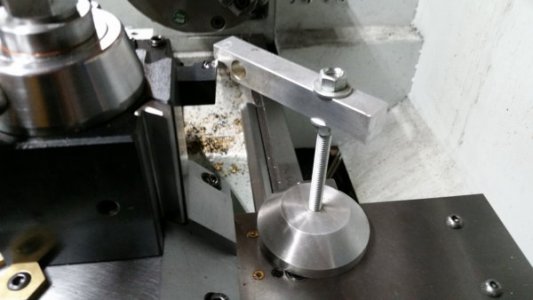
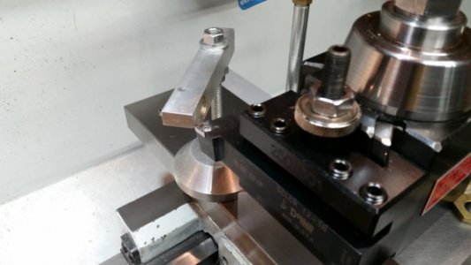
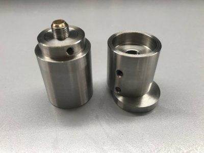
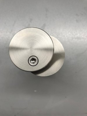
I finally got around to making a lathe tool height setting gauge. I got tired of breaking carbide inserts because the tool was never at exactly the right height. Here are some photos - in 316 stainless, 38mm diameter. It’s based loosely on what I saw done by Tom at Ox Tool on YouTube:
The height adjustment screw is 1/2-20, it’s locked in the base with a set screw, and the upper sleeve has a nylon-tipped set screw to lock it in position once adjusted.
I copied the swing-out top off the Hardinge version so I can check tool height against either against the bottom of the swing-out top, or by feel against the top surface of the main body.
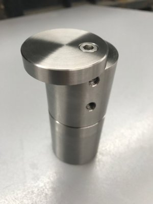
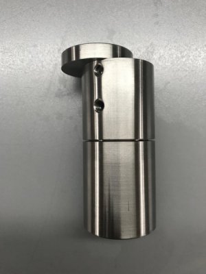
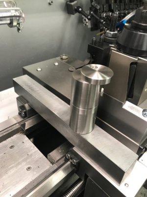
I use it in conjunction with a 1.5” square bar (precision milled) to span the carriage gap.
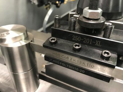
It’s very easy to discern the height of the tool relative to the reference point - my finger can detect a difference of under 1/1000th. Or the height gauge can be rotated around to test if the swing-out top clears the tool.
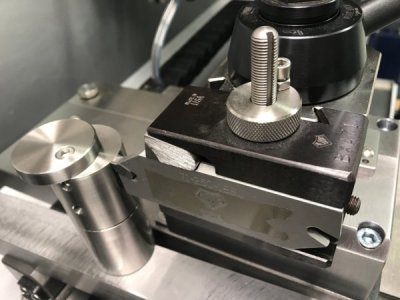
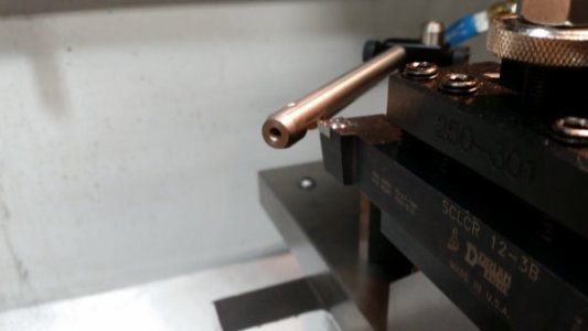
This is how I adjusted it to the lathe spindle center line. 3/4” end mill backwards in the chuck, checked for zero TIR. TDC referenced to zero with indicator.
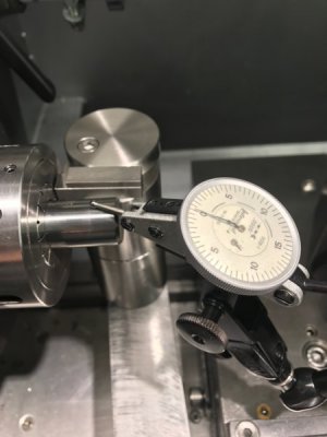
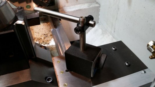
Carriage is moved so indicator is over the tool height gage with a 3/8” gage block stack on top - then the tool height gage is adjusted by (turning the base) to read zero, then secured with set screw. I've posted a video of the height adjustment method here if anyone is interested: https://www.flickr.com/photos/davidpbest/34194462773/in/album-72157682262435431/
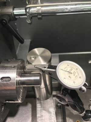
Hope this is helpful to someone - one of the most functional additions to my lathe, and has really helped - especially with part-off tool height setting.
The height adjustment screw is 1/2-20, it’s locked in the base with a set screw, and the upper sleeve has a nylon-tipped set screw to lock it in position once adjusted.

I copied the swing-out top off the Hardinge version so I can check tool height against either against the bottom of the swing-out top, or by feel against the top surface of the main body.


I use it in conjunction with a 1.5” square bar (precision milled) to span the carriage gap.

It’s very easy to discern the height of the tool relative to the reference point - my finger can detect a difference of under 1/1000th. Or the height gauge can be rotated around to test if the swing-out top clears the tool.


This is how I adjusted it to the lathe spindle center line. 3/4” end mill backwards in the chuck, checked for zero TIR. TDC referenced to zero with indicator.

Carriage is moved so indicator is over the tool height gage with a 3/8” gage block stack on top - then the tool height gage is adjusted by (turning the base) to read zero, then secured with set screw. I've posted a video of the height adjustment method here if anyone is interested: https://www.flickr.com/photos/davidpbest/34194462773/in/album-72157682262435431/

Hope this is helpful to someone - one of the most functional additions to my lathe, and has really helped - especially with part-off tool height setting.

