Lathe Threading, My Threads Look Wrong

Futterama

Registered
Registered
Joined
Dec 16, 2016
Messages
7
Hi forum,

I'm new here and have a question regarding threading on the lathe. My lathe supports both imperial and metric threads, but I only use metric 60° threads.

So the job in the hobby shop today is making internal and external metric threads with "tight" fit from EN AW 2011 aluminium. The thread size is non-standard, M19x1.0. I looked at M20x1.0 and M18x1.0 and took data from those.

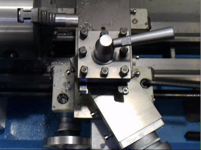
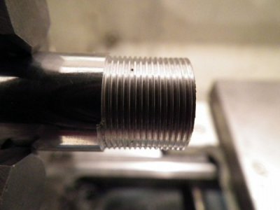
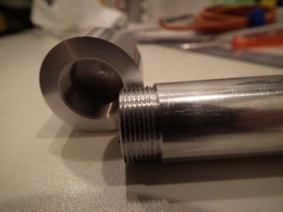
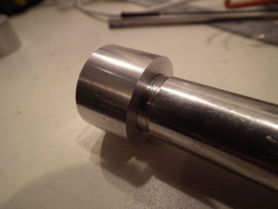
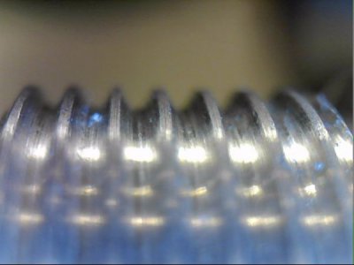
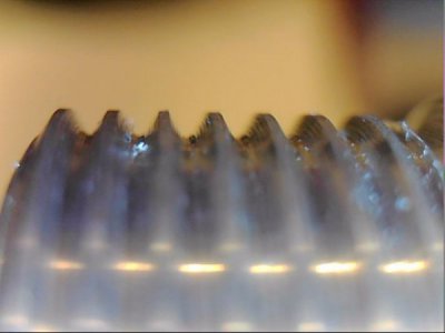
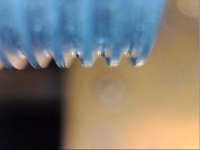
So I started with the external thread. Machined a piece down to 18.9mm, set up the 60° slide and calculated that I needed to move the slide 0.5775mm to get a thread depth of 0.5mm. The result is threads that does not look right at all, see the pictures (3 taken with a USB microscope). I think the flat top of the thread is way too wide.

I can find all these numbers online on metric threads, but not much information on how to use them for actually making the thread. The big unknown for me, is how deep do I need to cut the thread? There must be a "guideline" value that takes the 75% thread engagement into account, and then a maximum and minimum value depending on how much thread engagement you want.

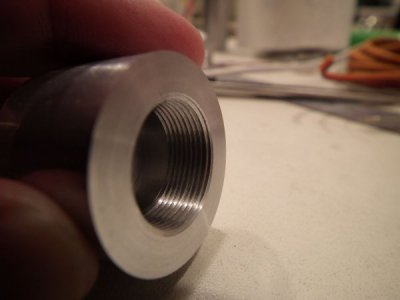
By several trial and error, I found that I could make the external thread from 18.9mm stock and thread 0.55mm into the surface. The internal thread starts with a 18.1mm hole and using 0.51mm thread depth.
1312636260326.jpg
1312636256878.jpg
1312636267838.jpg
DSCF4278.JPG
 
Looks to me you just need to go a little deeper. I suppose you do not a have a nut to check the external threads for fit?
 
Here is the pictures of the finished thread after "only" 4 attempts on external and 2 attempts on internal.
DSCF4283.JPG DSCF4284.JPG DSCF4285.JPG
 
No, I don't have a nut, I'm making my own mating part, M19 is non-existing in all the charts I have seen, so it's basically a custom thread size, nuts does not exist in this size.

Yes, I need to go deeper, but I would like to know how to calculate how deep I need to go.

It seems to be something like "add 10%" in my case here.

I did make the rod 18.9mm instead of 19.0mm and the hole 18.1mm instead of 18.0mm to add some tolerance, but that did not seem to be enough, maybe that just accounts for the radius on the cutter tip.
 
I always use the fit method. If I am making a custom thread part I make external and internal parts as a trial to get the dimensions very close before the real parts. I suppose you could calculate it but my attempts at that have not worked out in the past. Threads look real good!
 
I think I'd aim at a sharper point on the tool. Both the crests and the valleys look too broad.
If you have a piece of thin wire, (no wider than crest to crest,) you can measure over three (one on top, two on bottom, stick one end in a piece of Styrofoam) and calculate depth of thread. But for that you need a chart, and I can't find one for 19 mm, as you said.
This link
http://www.tribology-abc.com/calculators/metric-iso.htm
has a diagram at the top that may be of some help.
 
I can provide you with the thread data as well as a "over wires" number for checking the external thread. Usually it's best to make the external thread first and use it to gage the internal, since it's not practical to directly measure the PD without special instruments that few have.
 
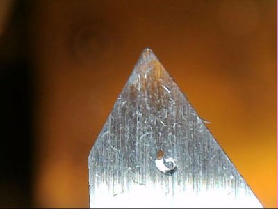
The threading tool is actually supposed to have a flat on the end of it, not a radius, but that is not a big deal other than that is can mess up your depth of thread. What is odd in the close up is that there appears to be steps on both sides of the threads. I could see steps on the right side from a compound angle that exceeds 30 degrees, but I have no idea how you are getting steps on both sides, unless you are reversing the lathe without backing the tool away from the work... (?) How about a close up of the sides of the tool?

Edit: A 1.0 mm thread will have the same profile dimensions regardless of the diameter of the thread.
 
Tony, I have piano wires in 0.3, 0.5, 0.8, 1.0 ect. Can you find over wires measure with any one of those for my thread?

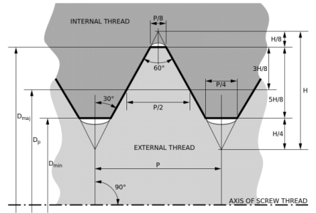
Bob, are you sure it needs to be flat for metric threads? All the drawings show a radius e.g. the attached one from Wikipedia. I didn't try to make any exact radius on there, I just took away the sharp edge really.

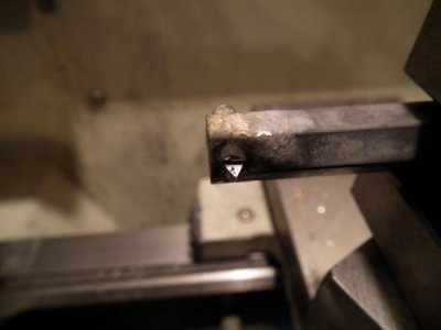
This is my first attempt at making internal threads. I made my own internal threading tool - a piece of hex stock with a piece of formed 4mm drillbit shank silver soldered in place. I think it works pretty well and it was easy to make with the materials I had at hand.

I am backing the tool when reversing, I think those steps are from the grinding process because the thread on the pictures attached in this post, was finished off with a 90° pass, so that both sides of the threading tool cuts that last cut for a "perfect" shape without steps.

ISO_and_UTS_Thread_Dimensions.png 1312639462628.jpg 1312639465219.jpgDSCF4286.JPG
 
Last edited:
The threads in the above post is the latest ones made. They now fit perfectly without binding and with the amount of tolerances I would like to get for this project. I made the internal threads the same depth (0.55mm) as the external this time. All attempts have been documented in Google Drive, so I can find them again later :)
 
Back
Top