- Joined
- Sep 20, 2012
- Messages
- 560
As it's raining I can't be 'volunteered' for gardening duties :scared: so I'm posting this instead..it is a n off shoot from here: http://www.hobby-machinist.com/show...d-on-iron-legs-why?p=77909&posted=1#post77909
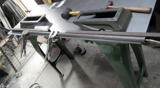
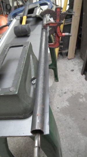
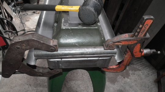
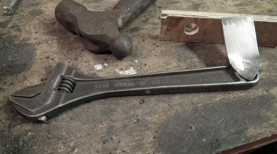
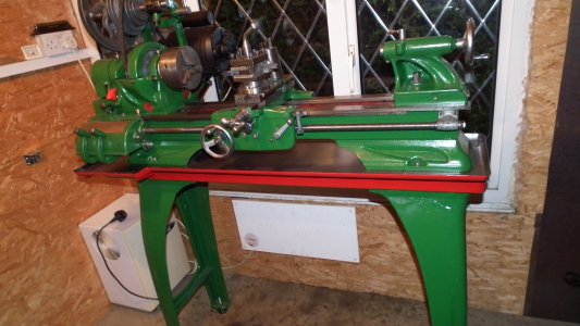
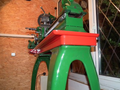
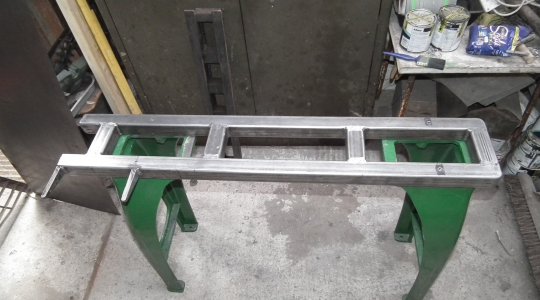
I made this to hopefully do a better job that a plank of wood, and look sort of the same style as a factory made one might look, it turned out to be much easier to do than I thought it would when I started, I reckon anyone who has a MIG even if they've never bent sheet metal before could do it too.
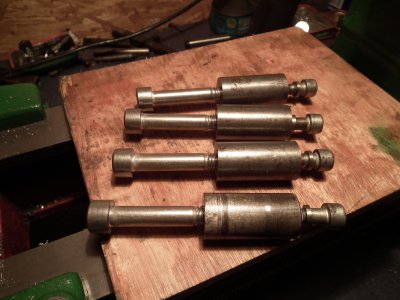
First I made these inserts to fit snugly inside some RHS steel, the larger bolts fit the cast iron legs and the smaller fit the lathe feet, the skinny washers are to centralize them in the oversize holes I made in the steel for wriggle room.
Holes where drilled in the RHS steel (de-burring the inside is essential) the inserts where slid inside then the lathe feet bolted to them using the skinny washers to centralize.
View attachment 42290
Short pieces where cut as braces.
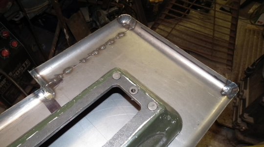
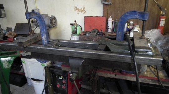
The frame was squared up, tacked together and welded together whilst cramped to a flat surface (I used an old lathe bed) to keep it straight, the vertical welds where done first, the top welds where ground before turning the frame over and re cramping to weld the underside ones. All welds where kept around 1" long and spread about to avoid distortion.
The ends where rounded off for appearance sake, in order to get a nice radius I cut pieces off a tube and straighten them into a J shape in the vise, and held in place for welding with some mega strong magnets robbed out of old microwave ovens, I have no pics of this because the god Pic fell asleep at this point and let me forget to take any.
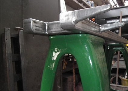
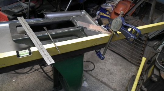
The 'outriggers' under the gearbox are too long in this pic, yeah I know measure twice cut once!
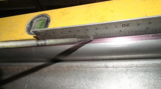
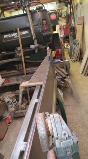
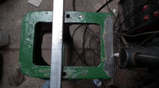
It is essential to always have at least one bolt screwed into each insert at all times before the ends are sealed, for obvious reasons. Tacking them in place is not a good idea as Atlas castings where not drilled with any precision...Maybe this is the real reason for the original use of wood, much easier for the customer to alter the holes to fit...line up the rule with the cross brace below to judge for yourself. Needless to say these holes needed work.
Lunch time now, so part two to come later.
Bernard


I made this to hopefully do a better job that a plank of wood, and look sort of the same style as a factory made one might look, it turned out to be much easier to do than I thought it would when I started, I reckon anyone who has a MIG even if they've never bent sheet metal before could do it too.
First I made these inserts to fit snugly inside some RHS steel, the larger bolts fit the cast iron legs and the smaller fit the lathe feet, the skinny washers are to centralize them in the oversize holes I made in the steel for wriggle room.

Holes where drilled in the RHS steel (de-burring the inside is essential) the inserts where slid inside then the lathe feet bolted to them using the skinny washers to centralize.
View attachment 42290
Short pieces where cut as braces.
The frame was squared up, tacked together and welded together whilst cramped to a flat surface (I used an old lathe bed) to keep it straight, the vertical welds where done first, the top welds where ground before turning the frame over and re cramping to weld the underside ones. All welds where kept around 1" long and spread about to avoid distortion.

The ends where rounded off for appearance sake, in order to get a nice radius I cut pieces off a tube and straighten them into a J shape in the vise, and held in place for welding with some mega strong magnets robbed out of old microwave ovens, I have no pics of this because the god Pic fell asleep at this point and let me forget to take any.

The 'outriggers' under the gearbox are too long in this pic, yeah I know measure twice cut once!

It is essential to always have at least one bolt screwed into each insert at all times before the ends are sealed, for obvious reasons. Tacking them in place is not a good idea as Atlas castings where not drilled with any precision...Maybe this is the real reason for the original use of wood, much easier for the customer to alter the holes to fit...line up the rule with the cross brace below to judge for yourself. Needless to say these holes needed work.

Lunch time now, so part two to come later.
Bernard


Last edited:


