

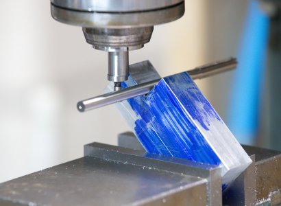
I was watching Joe Pi's video on building the steam engine and there is an episode where he made a 90 degree cut to accurately locate the position of the crank shaft bore so that the mounting surface for the bearing caps could be faced when it is positioned at a 45 degree angle. I needed to make a carriage stop for my lathe, so that looked like the perfect way to try out this technique to accurately position the vee for the carriage stop instead of scribing lines and working up to them like most videos show.
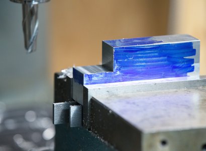
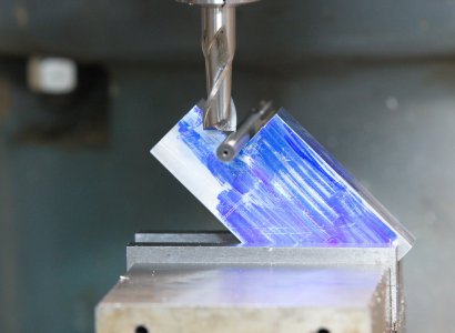
I cut a rabbet deep and wide enough for the vee to fully straddle the way and provide a bit of clearance so only the vee section is used to clamp it. Next I clamped the body at a 45 degree angle in my vice. I used the shank of one of my reamers to find the X and Z position of the intersection of the vee and the vertical edge. First I used my edge finder to locate the center of the notch in the X direction by touching off on the shank and moving over by the radius of the edge finder and reamer shank, then I installed an end mill and visually brought the end mill down to the point it was just touching the shank. My feeler gages were in the garage and I was too lazy to go up and get them, but that would be a better way to accurately find the vertical dimension without the risk of damaging the reamer shank or end mill tip. Once I had this position, I zeroed the knee dial and then I used some trig to calculate how much I needed to move the knee up for the end mill to be vertically at the intersection.
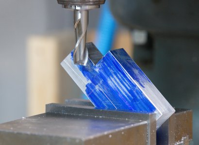
By using the radius of end mill, I moved it in the X direction to locate exactly, or as exact as my measurements, the transition from the angled portion to the vertical. From my drawing, I knew I wanted the slot for the vee to be 16mm wide. I made an initial cut and was pleasantly surprised it was actually where I wanted it. I then did a series of cuts until I was at the proper width.
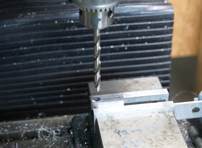
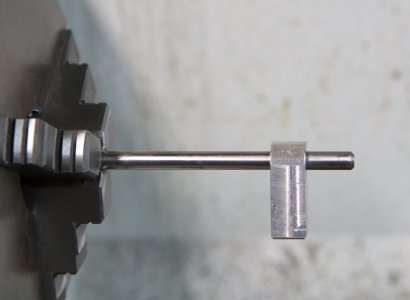
I planned on using some 9/32" rod I had for the shaft for the fingers, but had a senior moment and drilled it too big. Fortunately I had some 8mm rod and a reamer, but did not have an oversize reamer for the hole in the positioning fingers to allow for free rotation on the shaft. An O size drill came to the rescue, this is 0.001" larger than 8mm shafting and gave just the right amount of clearance for rotation and still keep the fingers from rocking side to side.
The first carriage stop I built could not be disassembled, so for this one I drilled and tapped a hole on the end of the shaft to allow for a withdrawl screw in case I need to remove the fingers at a future date, such as right after assembling it and finding out I screwed something up. Luckily that was not the case and hopefully it never needs to be disassembled. I used Bellville washers in-between the fingers to prevent any binding between the fingers.
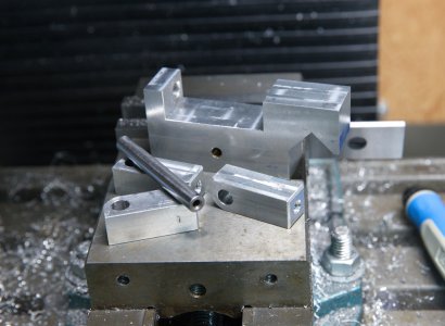
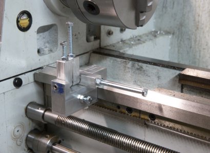
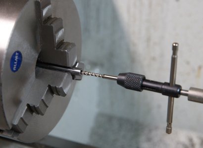
The last two pictures show the parts and the final assembly on the lathe. This was a nice and easy project that will help making some repetitive parts on a steam engine I am working on.
I cut a rabbet deep and wide enough for the vee to fully straddle the way and provide a bit of clearance so only the vee section is used to clamp it. Next I clamped the body at a 45 degree angle in my vice. I used the shank of one of my reamers to find the X and Z position of the intersection of the vee and the vertical edge. First I used my edge finder to locate the center of the notch in the X direction by touching off on the shank and moving over by the radius of the edge finder and reamer shank, then I installed an end mill and visually brought the end mill down to the point it was just touching the shank. My feeler gages were in the garage and I was too lazy to go up and get them, but that would be a better way to accurately find the vertical dimension without the risk of damaging the reamer shank or end mill tip. Once I had this position, I zeroed the knee dial and then I used some trig to calculate how much I needed to move the knee up for the end mill to be vertically at the intersection.
By using the radius of end mill, I moved it in the X direction to locate exactly, or as exact as my measurements, the transition from the angled portion to the vertical. From my drawing, I knew I wanted the slot for the vee to be 16mm wide. I made an initial cut and was pleasantly surprised it was actually where I wanted it. I then did a series of cuts until I was at the proper width.
I planned on using some 9/32" rod I had for the shaft for the fingers, but had a senior moment and drilled it too big. Fortunately I had some 8mm rod and a reamer, but did not have an oversize reamer for the hole in the positioning fingers to allow for free rotation on the shaft. An O size drill came to the rescue, this is 0.001" larger than 8mm shafting and gave just the right amount of clearance for rotation and still keep the fingers from rocking side to side.
The first carriage stop I built could not be disassembled, so for this one I drilled and tapped a hole on the end of the shaft to allow for a withdrawl screw in case I need to remove the fingers at a future date, such as right after assembling it and finding out I screwed something up. Luckily that was not the case and hopefully it never needs to be disassembled. I used Bellville washers in-between the fingers to prevent any binding between the fingers.
The last two pictures show the parts and the final assembly on the lathe. This was a nice and easy project that will help making some repetitive parts on a steam engine I am working on.
Attachments
-
 2021_Carriage_Stop_0002_FB.jpg254.4 KB · Views: 112
 -
 2021_Carriage_Stop_0003_FB.jpg251.9 KB · Views: 71
 -
 2021_Carriage_Stop_0006_FB.jpg288 KB · Views: 64
 -
 2021_Carriage_Stop_0007_FB.jpg280.8 KB · Views: 63
 -
 2021_Carriage_Stop_0008_FB.jpg264.4 KB · Views: 63
 -
 2021_Carriage_Stop_0012_FB.jpg276.2 KB · Views: 62
 -
 2021_Carriage_Stop_0013_FB.jpg199.4 KB · Views: 62
 -
 2021_Carriage_Stop_0014_FB.jpg221.7 KB · Views: 59
 -
 2021_Carriage_Stop_0015_FB.jpg281.4 KB · Views: 70
 -
 2021_Carriage_Stop_0016_FB.jpg293.9 KB · Views: 74
 -
 2021_Carriage_Stop_0002_FB.jpg254.4 KB · Views: 70
 -
 2021_Carriage_Stop_0003_FB.jpg251.9 KB · Views: 60
 -
 2021_Carriage_Stop_0006_FB.jpg288 KB · Views: 49
 -
 2021_Carriage_Stop_0007_FB.jpg280.8 KB · Views: 47
 -
 2021_Carriage_Stop_0008_FB.jpg264.4 KB · Views: 48
 -
 2021_Carriage_Stop_0012_FB.jpg276.2 KB · Views: 51
 -
 2021_Carriage_Stop_0013_FB.jpg199.4 KB · Views: 44
 -
 2021_Carriage_Stop_0014_FB.jpg221.7 KB · Views: 51
 -
 2021_Carriage_Stop_0015_FB.jpg281.4 KB · Views: 92
 -
 2021_Carriage_Stop_0016_FB.jpg293.9 KB · Views: 117