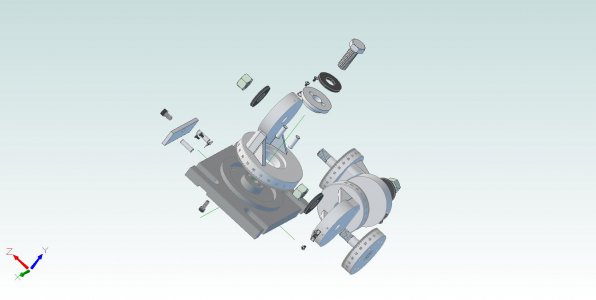
Latest Project: A Universal Milling and Grinding Fixture (see pics)

jgedde

Active User
Registered
Joined
Jun 23, 2011
Messages
786
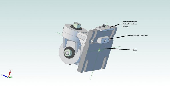
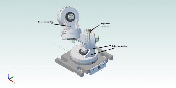
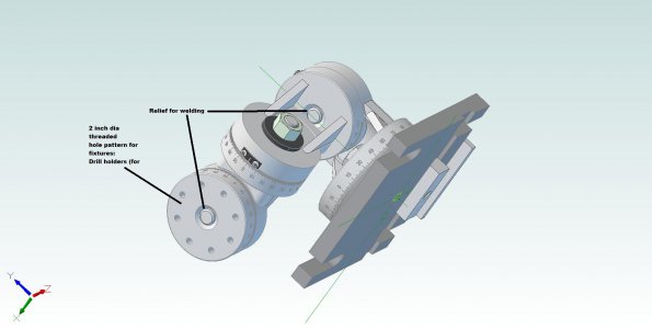
Here is my latest project. This is a universal holding fixture which can be used to machine compound angles, sharpen drill bits (standard method, or multi faceted), grind lathe bits, and more...

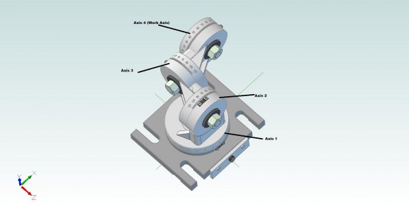
First, here are some 3D models:

Top Level Assembly 1.jpgTop Level Assembly 2.jpgTop Level Assembly 4.jpgTop Level Assembly A.jpg

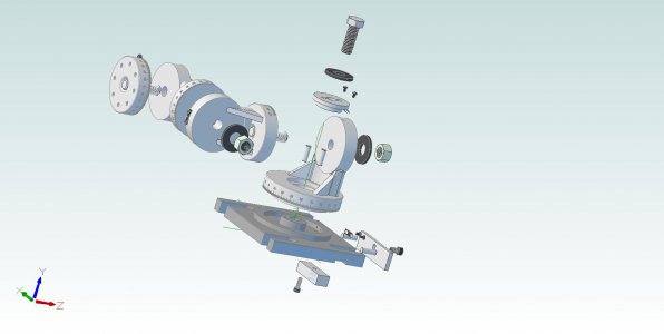
Now some exploded views:
Exploded 2.jpgExploded.jpg

And for the current progress (not including turret discs which are also done sans engraving)
IMG_1487.JPG

Since I have created 3D models (in Alibre 2012), I will be creating drawings. Of course I'll share these on this forum for those who want to make one too... Of course, as progress continues, I'll add photos so you can all see how it gets made.

I welcome all comments, suggestions, critiques!!!

John

Top Level Assembly 1.jpg Top Level Assembly 2.jpg Top Level Assembly 4.jpg Top Level Assembly A.jpg Exploded 2.jpg Exploded.jpg IMG_1487.JPG
 
Looking good John. Will be watching this one close.

"Billy G" :thumbsup:
 
Looks like a slick project. I'll be interested to see the plans.

Thanks,

-Ron
 
Shawn,

I'm using Ablibre 2012 Personal Edition. I've been an Alibre customer for several years. That being the case, I have a few extra features that I'm "grandfathered in for" that aren't part of regular PE.

The one's that matter are a three seat license (rather than 1), and the advanced import/export toolset. The latter allows me to import STEP files for piece parts (like hardware) from McMaster (this might be part of regular PE). I can also output Parasolid files for CNC, Solidworks, IGES, STEP, etc for import into ProE or Altium.

Again, I'm not sure if the standard Alibre PE allows you to import step files. Apart from that, there's nothing I did using my version you couldn't do with standard PE.

Now, I have just have to have Alibre make 2D dimensioned drawings for the parts and I'll have a complete set of paper plans (I'll post as PDFs).

The next step for me is to design some toolholders that fit the 2" bolt pattern on the fixture... Then, make drawings.

John
 
John,

Looks like a great tool if you make one, it really would do quite a bit ot accurate grinding. Thats an idea for sometime down the road fer sure. Thanks for the heads-up for what is hopefully coming next. Any ideas of the materials list and time frame for completing it yet? All your stuff is so slick I gotta figure it out like you did. Great work as usual.
Bob

Bob
 
Thanks for the good words Bob!

As for timeframe, it'll take as long as it takes. That wasn't meant to be snotty, but at the rate I'm currently going it may be a month or two to complete. Too much stuff going on as of late.

Plans I can post should be forthcoming in about a week.

Materials are from my scrap bin, but I did design it with plans for others in mind. That said, it generally uses standard size materials machined slightly undersize for a nice finish. For example, the graduated pucks are made from 2.75 round stock turned down to 2.70 to get rid of any scale, scratches, dings, etc thus allowing bottom of the bin materials to be used.

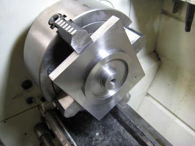
The base plate would likely be the only somewhat pricey piece being made from 1" thick stock. Mine was made from an old cast steel microscope base I had in the junk bin. Another option would be to use a 0.750 thick piece and weld on a 1.25" dia protrusion (which I did because the scope base was only .850 thick). The protrusion is the center section in the chucked up piece in my photo above. I simply drilled two holes in a disc, welded it on through the holes, then machined it to OD and faced of the weld beads. You can't tell it is actually two pieces.

John
 
Here's the first drawing. I'm not a guru when it comes to GD&T, but here is a drawing of the base that gives all pertirnent dimensions... Please feel free to review and comment (especially those well versed in GD&T).

View attachment Base.pdf

John
 
Last edited:
Doesn't look too bad, John. I will make a couple of comments on your GT&D. A parallelism callout will not have a reference to a circular tolerance zone as you have drawn on the 3.750 OD ring. Same with the flatness callout on the bottom of the base, Datum A. The True Position on the 0.2490 reamed holes should be referenced to a diameter such as the 3.750 ring OD rather than a flt surface as you have drawn as Datum B. Depending on what you have fitting the reamed holes, I presume dowel pins, the mating part will have a feature that fits closely somewhere, and that's what you should look for to determine the reference datum for their True Position.

That's all I see at a glance. I'll study it a bit more and see what else I can find. I don't see any concentricity callouts, which I would expect to see, given all the parts that must rotate with some precision.

Thanks Tony, I was hoping you'd chime in! :))

1) What I was trying to indicate was that the plane on top of 3.750 dia boss should be parallel to the base's bottom. How should that be done?

2) The center section (the 1.250 dia) is the pilot diameter for the base turret and nothing else, so concentricity is taken care of. The 3.750 and 2.875 diameters don't need to be all that concentric to the 1.250 diameter apart from aesthetics. See runout of the turret with respect to the pointer would just look bad.

3) As far as the dowel pins: they serve as an anti rotation device for the mating part (the base clamp). The goal is to prevent the tightening of the center bolt from rotating the base turret. The mating part needs to slide freely, but with no side play, over the dowel pins. So, their location with respect to holes in the mating part is important. I'm not sure how to go forward given this requirement. Can you offer any advice?

I'm currently enamored with true position since we have a design (and print) at work for a near zero backlash planetary gearbox (for a satellite) that specifies TP to 0.0001" from multiple datums (we need the low friction of a planetary with the low backlash characteristics of a Harmonic drive).

We've found only one guy in the country who can make these parts consistently! He came to our shop and set up our wire EDM machine with fixtures that we're nothing short of amazing! Now we can do it too! The trick was to use this fixture to move the workpiece rather than move the wire. He's relying on our wire EDM machines incremental rather than absolute accuracy. The wire simply cuts a hole, but never moves more than 0.050 or so.

His fixture used ceramic dovetails, indexers with sub arc sec accuracy. Even our master machinist said he "felt inadequate" in the presence of this guy!

Getting back to my design, ANSI 14.5m is a tough thing to get my mind around. I know how it all should fit together in my mind, but getting it on paper is a horse of another color...:( Makes me appreciate mechanical engineering more and more. Maybe I should stick to high reliability electronics design and leave the precision to the pros? Just kidding...

John
 
Doesn't look too bad, John. I will make a couple of comments on your GT&D. A parallelism callout will not have a reference to a circular tolerance zone as you have drawn on the 3.750 OD ring. Same with the flatness callout on the bottom of the base, Datum A. The True Position on the 0.2490 reamed holes should be referenced to a diameter such as the 3.750 ring OD rather than a flt surface as you have drawn as Datum B. Depending on what you have fitting the reamed holes, I presume dowel pins, the mating part will have a feature that fits closely somewhere, and that's what you should look for to determine the reference datum for their True Position.

That's all I see at a glance. I'll study it a bit more and see what else I can find. I don't see any concentricity callouts, which I would expect to see, given all the parts that must rotate with some precision.

Tony, How about this one? View attachment Base.pdf

Thanks,
John
 
Back
Top