Large dials for a South Bend 14 1/2

Mark_f

Registered
Registered
Joined
Jan 16, 2020
Messages
5
I am attempting to make large dial conversion for a South Bend 14 1/2 lathe for a friend of mine. I took measurements from his original setup but changed dimensions to a 3 inch diameter dial. These parts were made on my 9 inch S B lathe.
20171024_195005_HDR.jpg
20171024_194957_HDR.jpg
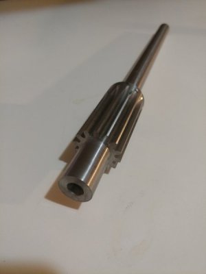
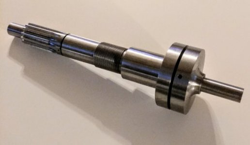
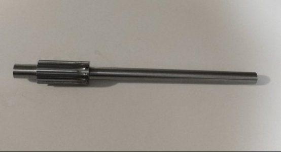
This was my third attempt at cutting this gear. I learned a lot on the first two tries. Third time was a charm.
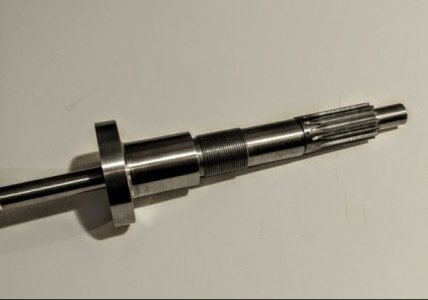
We didn't want to alter the original parts so I had to make a new gear and shaft as the shaft had to be extended several inches.
20171024_195024_HDR.jpg
20171024_195018_HDR.jpg
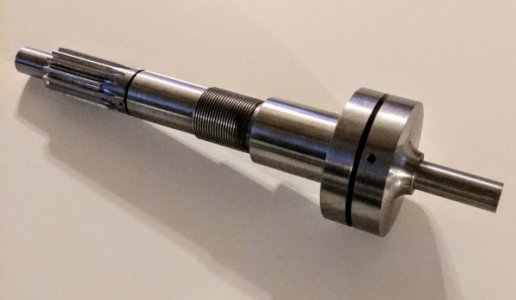
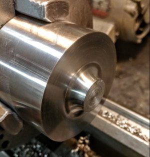
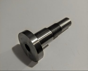
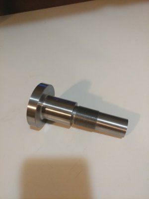
This is the new bushing with dial face. It is 6" long and I bored and reamed a .750" hole through it. It will get a bronze bushing in each end to support the.625" diameter shaft.
20171024_195038_HDR.jpg
This is what the parts look like assembled. I will make the acme screw , the graduated dial, and put needle thrust bearings in each end.
This unit will be for the cross slide.
20171024_171242_HDR.jpg
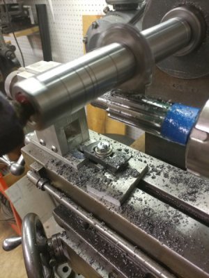
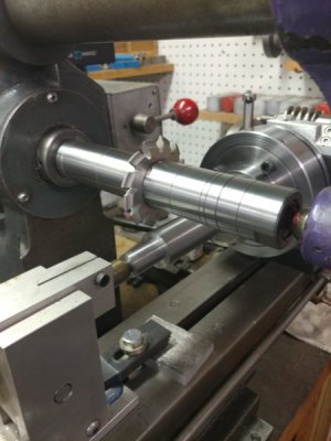
Cutting the gear on my Burke mill. It took hours to cut the gear. The first round was .100" depth of cut. Second round was .054" depth of cut, then a .001" finish cut. The spindle speed was 154 RPM, the feed was about 1" per minute.
20171022_154531_HDR.jpg
This is the gear cutting setup using the new arbor I made.

.......More to come.
 
20171026_115337_HDR.jpg
There is a bronze bushing in each end of the body to support the shaft on the ends.

20171025_174024_HDR.jpg
I got some mystery metal to make the dial.


20171026_115333_HDR.jpg
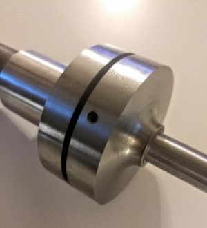
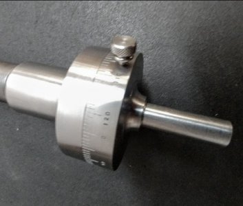
This is the dial and dial bushing. I still have to mark the graduations on the dial, but first I want to test fit it in the lathe.
 
WOW, we just talked about that and it is almost complete. VERY NICE can not wait to see it finished.

I've worked on my parts for the saw and OH how I love this lathe now. 1.5 horse and quite, makes it such a joy to run.
 
Super , Mark as usual another fine example of true craftsmanship. I so enjoy studying the items you build. You really understand what being a machinist is , no limits or real boundaries on builds.
 
I took the assembly to my friends house to check the fit on his lathe.
20171026_115337_HDR.jpg
(The small hole in the dial will be for the lock screw)
Everything fit great. The gear turns smooth and only has a few thousandths backlash. Next will be to finish this assembly and mount it permanently in the lathe.

I machined a .205" deep pocket in the body so the bearing and bushing would be flush with the end of the body. I machined .145" off the other end of the body to allow for the other thrust bearing and .001" preload.

20171027_152719_HDR.jpg
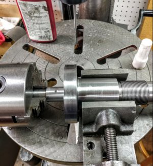
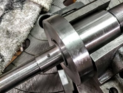
There is a bushing that preloads the thrust bearings. I put the assembly together and used a small chuck I had to hold the busing against the bearings while I drilled and pined it.

20171027_152921_HDR.jpg
I locktited the 1/8" dowel pin in the shaft. ( I then realized I didn't need to as it was a press fit and is captured by the dial.

20171027_153713_HDR.jpg
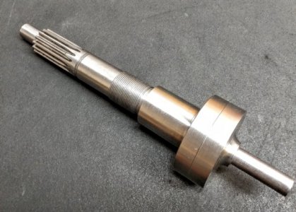
This is the assembly. You can see the thrust bearing between the gear and body. The bushing sticks out.003" past the dial. This is so when the handle is installed, the dial will rotate freely. So far, everything is perfect and fits great. The next step is to graduate and stamp numbers on the dial.

We decided to keep the .125" per turn, but if there is room without crowding, we will put 250 graduated marks so the dial reads like his other lathe and reduce confusion going back and forth.
I also realized I do not have a hole plate for my dividing head to make 125 or 250 graduations. It requires a 25 hole pattern. I do have a 20 hole pattern that will make a 25 hole pattern by going 1 turn and 4 holes.

20171027_155434_HDR.jpg
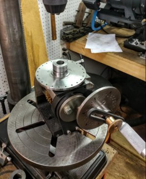
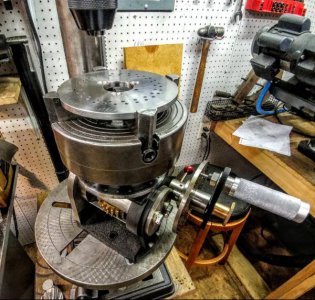
I set my dividing head on my drill press and turned the head to the 90 degree position ( I am glad l built this feature into the dividing head).

20171027_161154_HDR.jpg
I mounted my 4 jaw chuck on the head and put the plate to drill in the chuck. I set the dividing head up with the 20 hole plate and now I am ready to make the 25 hole pattern to graduate the dial. After the dial, I will make the lead screw and finish the cross slide. ( Then start the compound, and then the tail stock upgrade).

So far this has been an exciting project, but I had to modify my homebuilt dividing head by making a new spindle for better accuracy ( for the better). Then I had to make an arbor to hold the gear cutter to make the gear. Now I have to make a hole plate for the dividing head to be able to graduate the dial. I keep having to make tooling to do the needed operations, but that is the fun part and the accuracy of the tooling I made is amazing to me ( but I took care to hold very tight tolerances).


Lots more to come........
 
The amount of work you do to produce the parts are just above and beyond the norm. That's the reason your work is just beautiful . Your dividing head is a prime example it looks better then most sold on the open market. If I were your son I'd be so proud work with you. Stick to excellence we only can try you've achieved it.
 
Silver
Do not cut your self short, with a teacher like Mark we can all learn and put it into practice and one day we will be able to make great looking and working projects. I have a lot of parts I taken from things I scraped out and if I think I can use it I'll save it. Today I found a piece of shafting that someone used as a punch, one side looked like a mushroom from being beat on, look like it was 20 years in bad weather. Wire brushed it and turned it on my lathe and a brand new part that looked new. Practice might just make us better than we once were.
 
Oh I don't , I can do and have done many super tight jobs under government inspectors . My hold up or inability lies in the fact I'm bed bound , caused by bulging discs in my lower back. Most items I make to use I don't go the extra to put krinkle paint or polish to mirror finish. I do where a item needs to have slip clearance , no burrs allowed to gall . I have the tools most anyway just not able now. I've even made a built my own power sliding door on my van , and devised the installation of a wheelchair lift with about 1/8" clearance on both sides and top of door too. I do like when tools look super as with Marks builds .
 
I finally got the dial finished. My friend supplied a piece of nice looking mystery steel to make it but it was kind of hard cutting. When I tried to engrave it, it would not engrave well. The lines were rough and not straight, so I had to find another piece and make the dial over. I got it done and engraved. It came out good this time.
20171030_131613_HDR.jpg
 
Back
Top