[Newbie] Introduction And Questions.

Jim_Hbar

Registered
Registered
Joined
Feb 7, 2016
Messages
36
First thread here, and I’m kind of a newbie to this Hobbyist Home-shop CNC’ing stuff – but I believe I come at it from the opposite direction than the majority do….

I’m a semi-retired mechanical engineer and I worked in industry for 30+ years designing and supervising the design and commissioning of high speed industrial machinery. In our designs, we used hydraulic and AC servo’s for many applications, and did closed loop motion control on multi-axis machines - comparable in sophistication to the motion control used in flight simulators - but without the fragile cargo. So I believe I have a good understanding of the dynamics and physics involved, and the merits of the various approaches to closed-loop motion control. But my experience is with industrial gear that started at about $10K per axis and went up from there, and we let the EE’s deal with the motion controllers and PLC interfaces.

Fast forward to today - I have a Clausing 8520 in the shop that I’d like to do some prototyping on. I would ultimately need 4 axes.

Ball-parking some numbers, if I aim at 200 IPM on the X and Y axes with standard 5mm lead ball-screws, a 100W servo with a 3:1 drive will give me about 250 LBF with 3000rpm at the motor.
For the Z axis, I would likely power the knee - aiming for 100 IPM, so would need a 6:1 total reduction to have 500 LBF available at 3000rpm. This is way more than I need, but there are not significant cost differences between 50 to 400 watt hobby class servo’s that I’ve found (DMM’s) in my searching to date. Therefore, I could quadruple the output forces for little additional cost - with the very real danger of breaking things!

But it appears that 3-axis Ebay/Chinese Stepper kits can be had for about 1/3 the price – if one can find any reliable Torque vs. Speed curves that can be believed.
So far, I’ve only been able to find decent graphs on the Leadshine motors.
Using 50% of the torque values published, as the basis for the selection, it would appear that NEMA 34 size steppers, with 8 lead parallel connections, would just about match the forces available from the above 100W servo.

The advantages I see for using steppers are; simpler mounting, lower hardware cost, less (and cheaper ) wiring, potentially easier commissioning with fewer parts to fail. I would guess that direct coupled steppers could be installed in less than ½ the effort, compared to doing belt drives and covers.

So, the questions I have are:
- Am I crazy to consider steppers?
- Does anybody have believable torque curves for the Ebay/China Nema34 steppers?
- Is the DMM servo gear acceptable, or would I be better off going with EBAY surplus industrial gear, in brands I know? Any preferred EBAY sellers?

Any insight would be appreciated.
 
Welcome aboard Jim!

Our backgrounds are similar, most of my work in the last 20 or so years has been in high end servo systems (up to about 35KW) in industrial equipment. I lean more towards the electrical side but can do both.

Man, you ask some tough questions. To start with I have never heard of DMM until you posted. I took a look at their website, looks like full featured and inexpensive equipment. I will research them a bit further.

Hmmmm.....To stepper or servo, that is the question. I have used both and in combination. I am running NEMA34 1280 in/oz (~80 in/lb) steppers on my 4x8 router with good results. I have tested it up to 600IPM rapids, but I have limited it to 150IPM, I'm not in that big of a hurry. The motors are geared down 1.3:1, and the lead screws are 0.25 pitch. Just to put this perspective, the Y lead screw is 1.5 inch dia, and about 10 ft long, and the table is 1 inch aluminum plate with 3/4 inch Delrin over that, so a lot of mass.

On my 10x50 mill I have Baldor DC, 34 in/lb servos with Fenner drives on the X & Y axis, and a NEMA 34 1280 oz/in stepper on the Z. The NEMA 34 is really too much motor for the Z and I have it current limited to about half of it's rated current to prevent breaking things. I'm running a 15:1 reduction on that one. It will easily run 100IPM, but I have it limited to 60IPM.

On both machines I have Renishaw LM10, 1 micron, magnetic linear encoders. The closed loop is the key to making things work correctly, and it's my preference to put the encoders on the load rather than the leadscrew.

Normally you would want to double the torque on a stepper vs. a servo to prevent decoupling under accel/decel.

I have used the Ebay steppers and drives with no problems, but not sure about the torque curves. I have not noted any torque problems, but I always oversize the motors, you can always cut them back a bit if needed.. On my equipment I have been using Automation Direct steppers. I have noted a difference in the drives. The $275 Automation Direct drive is much smoother than the $65 Wantai drive from Ebay. Automation Direct has less expensive drives, but I use the high end one because it has an analog input and can be run in velocity mode as opposed to step & direction.

The motion controller is really the key to a good running system. My preferred vendor is Galil Motion Control. I did notice that DMM has an interface card that is compatible with Mach3. I need to look at some user reviews on that one. I am not a real fan of Mach3, but it is very popular software.

I probably generated more questions than I answered, but maybe this will get you started.
.
.
 
Jim - Thanks for the response.......... 35kW only?:D:D I can't remember the biggest hydraulic servo we did, but it had about 100gpm at 3000 psi available (120kW?)...
I see you're from the PNW - I'm north of you across the line..

The challenge with selecting steppers is the torque available at speed - there just isn't any! Especially compared to a similar frame sized and properly geared servo.. And to get any torque, one needs to use an 8-lead motor wired in parallel, or find a driver that can run them uni-polar.. Searching through the Leadshine torque curves, it's tough to find a stepper that is rated for much more than 1 Nm at 1000rpm (= .1 kW) - and then when you derate it 50% there is really only .05kW available... Or only about .025kW if it's a 4 lead motor..

I am running NEMA34 1280 in/oz (~80 in/lb) steppers on my 4x8 router with good results. I have tested it up to 600IPM rapids, but I have limited it to 150IPM, I'm not in that big of a hurry. The motors are geared down 1.3:1, and the lead screws are 0.25 pitch. Just to put this perspective, the Y lead screw is 1.5 inch dia, and about 10 ft long, and the table is 1 inch aluminum plate with 3/4 inch Delrin over that, so a lot of mass.

That Y-axis is setting my alarm bells off!! - especially that screw inertia!
You must have very mild accelerations, negligible friction, and a well tuned motion controller. But it is a good data point for me to throw some numbers at.. With the closed loop control on that axis, a few lost steps here and there doesn't mean anything, so you can push those motors at least twice as hard as somebody that is doing open-loop step control..
With the 600IPM rapids, you are spinning that motor to 3120 rpm! And the Leadshine curve for their biggest NEMA34 (which is a 118mm long body - similar to yours ?) only goes to 2400 rpm..

I read through your Z-Axis web-page, and you did an excellent job on the integration of that stepper into the mill... I really like your design solution for uncoupling the drive, and the gear case!!
And with that motor on there, you can use it for an arbor press if you really need to!;)

Using steppers, the shaft sizes are a real indication of what the motors are capable of, and the only thing in my former life that used a 1/4" shaft was a basic encoder - and we always put them in another box with a real shaft on it.. Those dinky little 1/4" shafts on the Nema23 steppers just don't feel right, but in reality are likely the best choice for my application...

The design engineer in me wants to just source some Mitsubishi drives off EBAY (I know the distributor up here, and could likely get some "behind the scenes support" if needed), get some MTS probes from my buddies to mount on my axes, and then figure out how to deal with the controls. But the Scotsman in me says Mach 3/4 with steppers is known and easy and probably 25% the cost (and effort) and 75% of the performance for a machine I will only use occasionally..
 
Last edited:
That Y-axis is setting my alarm bells off!! - especially that screw inertia!
You must have very mild accelerations, negligible friction, and a well tuned motion controller. But it is a good data point for me to throw some numbers at.. With the closed loop control on that axis, a few lost steps here and there doesn't mean anything, so you can push those motors at least twice as hard as somebody that is doing open-loop step control..
With the 600IPM rapids, you are spinning that motor to 3120 rpm! And the Leadshine curve for their biggest NEMA34 (which is a 118mm long body - similar to yours ?) only goes to 2400 rpm..

You are correct, I am not pushing things too hard. Still, the motor has plenty of power. The body on my NEMA 34 steppers is 127mm, bipolar, 4 wire.

I got to thinking about your numbers above. A little error on my part, I went out and actually measured the Y screw. Turns out I had the pitch way wrong. It's a 1 inch pitch, 4 start screw, geared 2:1. So I'm only turning the motor 1200 RPM at 600 IPM. The drives are set up to run 20,000 steps per revolution.

I read through your Z-Axis web-page, and you did an excellent job on the integration of that stepper into the mill... I really like your design solution for uncoupling the drive, and the gear case!!

Thank you for the kind words. :tranquility: A lot of thought want into that.
Fast forward to today - I have a Clausing 8520 in the shop that I’d like to do some prototyping on. I would ultimately need 4 axes.

You might be interested in this, I recently added a 4th axis. http://www.hobby-machinist.com/threads/4th-axis-build.40642/

On your 8520, NEMA 34 steppers would be more than enough, unless of course you decide to go with servos. ~30 in/lb servos would be overkill, but it never hurts to have extra power, you don't have to use all of it;)
 
It's a 1 inch pitch, 4 start screw, geared 2:1

I believe you meant "lead", not pitch....:D:D

Thanks for the link to your 4th axis build - It would never occur to me to build stuff the way you do - I'm too used to designing for pure function and manufacturing ease/speed, with no thought to the aesthetics.
To mount the stepper on the rotary table, I would have had a CAD pattern water-jet cut, c/w slots, bores and holes, and fabricated a belt cover out of 16gauge.. A few zaps with the MIG, and done!

I'm leaning towards Nema 23/24 size Steppers - at speed, they can do just about as well as the 34's.. By the time the smoke clears, putting 3 big 34's on the knee adds 25 to 30 lbs that has to be moved by the Z-Axis.
 
You are correct, lead. :)

I just design to build with what I have to work with, and I get a chance to show off a bit.;) Most of my machine work anymore is prototype and tool & die, and normally not in a big hurry.
 
Mr. Dawson:

Do you have any pointers on where a guy should look for connectors for the cabling to the steppers? - I'm looking for something that is approaching ip67 or 68 at the motors in particular, and bulkhead mount at the enclosure..
Need to handle 7.5ish amps @ peak.

Of course, what I would normally do are MS connectors, but it just seems wrong to spend double the money (or more) on the connectors than for the steppers and drives..:eek:

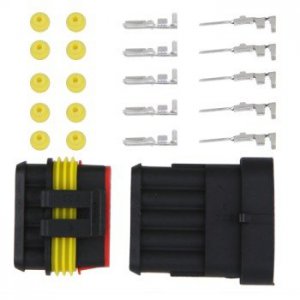
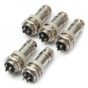
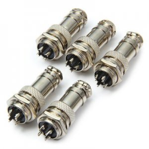
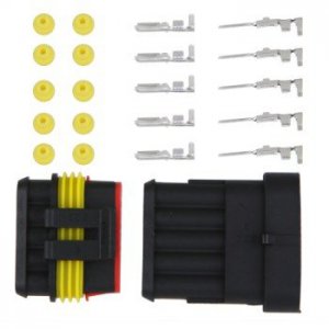
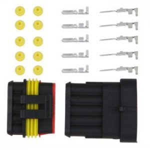
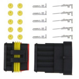
These things are cheap on EBAY, and I would use them at the can.
1421600811334-P-2355561.jpg

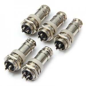
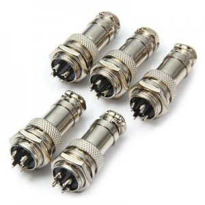
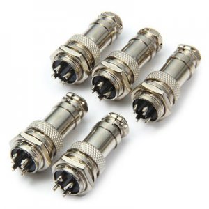
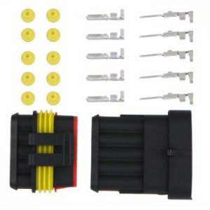
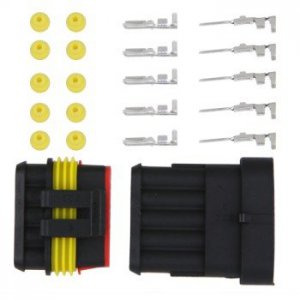
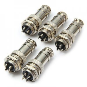
These are cheap also - and I'd use them at the motor.

31itWbyjWhL.jpg
Neither is ideal - I would connect the shield at the motor with the 5th pin in the flat connector.
Then on the aviation style connector, do you think relying on the connector body itself for the shield grounding connection would be okay, or should one pull do a separate connection for that?

1421600811334-P-2355561.jpg

1421600811334-P-2355561.jpg

1421600811334-P-2355561.jpg

31itWbyjWhL.jpg

31itWbyjWhL.jpg

31itWbyjWhL.jpg

1421600811334-P-2355561.jpg

31itWbyjWhL.jpg

1421600811334-P-2355561.jpg

31itWbyjWhL.jpg
 
You don't really need a shield on the stepper motor cables, at least I have never had a problem, even with unshielded motor cables laying next to sensor wiring. On the other hand I always wire the limit switches and other sensors active low. Makes them pretty much noise immune. On big servos I do use shielded motor and resolver cables.

Most steppers are about an IP40, pretty much not sealed at all. Using IP67 connectors seems like overkill. I would splice the motor cable to the pigtail on the motor and heat shrink. The Automation Direct motors and cables are furnished with an unsealed 4 pin Molex or equiv. Never had a problem yet. Their cables are not shielded.

For the panel end, I would look at these if you really need a disconnect point.

http://www.automationdirect.com/adc...Terminals)/Inserts_(Size_3A)/ZP-MC03A-1-MS003

These are IP66 rated.

I don't like to use any connectors between the drive and the motor, it just adds another possible failure point. I would rather run the cable into the panel with a strain relief and a drip loop, and wire direct to the drive. Where possible I enter the bottom of the enclosure. Now on my 4th axis, I do use the furnished 4 pin connector at the motor, the other end is wired directly to the drive.
 
Thanks!
I once wasted two weeks in Northern Alberta, due to a PLC blue hose being run back in the power cable tray. I don't want to repeat that experience for the sake of a couple bucks.
And being a mechanical engineer, I'm biased to making things easy to change after the flexing and possible mechanical damage to the cables. I'll ponder on the connectors

A friend that has a computer store gave me an old dead server box, and I'm going to use it to mount the 4 drives, the Eding interface board and power supply(s).
My computer is going in there also, but it won't take up much room.. It's a Windows 10 PC, with a quad core processor for US$99, in a package the size of a cell phone.
With the Kangaroo PC, I have to use USB to connect to the interface board, thus my concern regarding shielding.
But that shielding is really only a concern inside the box, and a bit of planning should deal with that.
 
My computer is going in there also, but it won't take up much room.. It's a Windows 10 PC, with a quad core processor for US$99, in a package the size of a cell phone.
With the Kangaroo PC............

That's a cute little PC. I'm in the process of rewriting my CNC software so it will run on Win 10, I might just have to give one of those a try. I don't need a heck of a lot of processing power, the motion controller does all the heavy lifting.
 
Back
Top