-
Welcome back Guest! Did you know you can mentor other members here at H-M? If not, please check out our Relaunch of Hobby Machinist Mentoring Program!
You are using an out of date browser. It may not display this or other websites correctly.
You should upgrade or use an alternative browser.
You should upgrade or use an alternative browser.
Install a VFD on a Grizzly G0602 10x22 Lathe ?
- Thread starter HMF
- Start date
- Joined
- Jun 12, 2011
- Messages
- 581
Although I do not have a Grizzly G0602, I do have a G4000 and a G6672, both with VFD's. Actually all I did was replace the original motor with a same frame 3 phase 1HP and wall mounted the VFD controller. I eventually plan to install remote controlling, but the wall is easily within reach and works great for now so I may never get around too it.
- Joined
- Jun 12, 2011
- Messages
- 581
Oops, I mean a G9972!
- Joined
- Sep 22, 2010
- Messages
- 7,223
November X-ray link=topic=2765.msg18893#msg18893 date=1310752662 said:Although I do not have a Grizzly G0602, I do have a G4000 and a G6672, both with VFD's. Actually all I did was replace the original motor with a same frame 3 phase 1HP and wall mounted the VFD controller. I eventually plan to install remote controlling, but the wall is easily within reach and works great for now so I may never get around too it.
When you get a chance can you please show us some photos of the VFD, enclosure and wiring? Thanks!
Nelson
Last edited by a moderator:
- Joined
- Aug 4, 2011
- Messages
- 2
yes mine is converted. used a direct replacement D80 frame lesson motor and teco vfd. as mine is converted to CNC i did not incorporate any of the stock wiring. i have the 3 wires coming from the wall outlet to the VFD and then the 4 wire cable coming from the VFD to the motor. that is really all that is to it for doing it like that.
- Joined
- Sep 22, 2010
- Messages
- 7,223
I posted some photos onto Ed's post- if anyone wants to comment on what is going on in the photos.
There is a HUGE enclosure- inside is the VFD and various wires.
Personally, I would like my VFD open for air flow.
Second, I would like to know what all those wires on terminal strips are for. Seems a LOT of wires considering the VFD provides speed and forward and reverse. Third, the original panel on the lathe was drilled with a scroll saw to add more dials and/or buttons. I would like to know what was added and why.
Can your friend Henry perhaps ID the items in the box and on the panel.
I need this "idiot proofed" for me.
Nelson
- Joined
- Aug 4, 2011
- Messages
- 2
all the wires he has in there arent actually required. i believe he just pulled the electrical components out of the back of the lathe and put them in the box to make wiring easier. the front is a tachometer so he can tell how fast the spindle is moving along with knobs to adjust the speed and i think one changes the mode it reads in.
but as i said you can completely get rid of all the stock electronics with the VFD install. This of course will get rid of things like your estop, which in my case wasnt necessary as i have one wired into my cnc driver that kills the power.
but as i said you can completely get rid of all the stock electronics with the VFD install. This of course will get rid of things like your estop, which in my case wasnt necessary as i have one wired into my cnc driver that kills the power.
- Joined
- Sep 22, 2010
- Messages
- 7,223
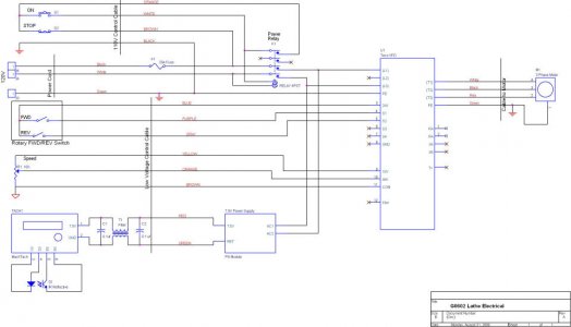
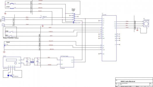
In the upper left are the 220 one phase lines coming in, but I don't understand what device is being used. Looks like one 110V lead is being used for on/off and the other for something else. Also don't understand what the relays are for. UGH!
Here are the deszigner's comments:
"This design includes the original magnetic contactor except I moved it to the external box with the VFD. It uses all original switches except that the direction switch is now low voltage. The tachometer is optional. The schematic shows the cable breaks between the lathe and the control box. I used connectors for these breaks but this is optional. The control box is an off the shelf item from the Home Depot electrical isle. I included a fan which probably was not necessary which is why it is not shown on the schematic."
"I added connectors for my low voltage and 110V cables so I can disconnect the new control box from the lathe."
"The box contains the VFD, the original contactor, a terminal strip, a wall wart for the tachometer, and the optional fan. The fan blows air up through the VFD and out a passive vent on the top of the box."
Nelson

Last edited by a moderator:


