Input On My Pieced Together Rpc

fleckner's garage

Registered
Registered
Joined
Jul 11, 2016
Messages
66
I am new to running 3 phase machines and i have a pieced together RPC that i'd like some input on what people think about it, if its ok, etc?

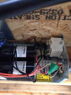
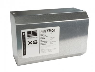
To start i have a TEMco 4-8hp static phase converter that is supplied by a manual disconnect 30amp 220v single phase circuit from a 100amp sub panel in my garage.
XS_01new.jpg
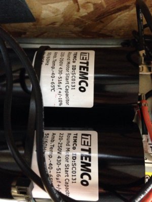
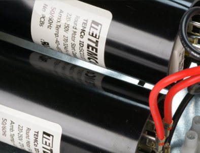
Appears to utilize only one start capacitor and one run capacitor? this is where my electrical knowledge is severely lacking.
XS3_08new.jpg

from this static converter I have 4 wires running to a junction box T1.T2.T3 and a ground. from this junction two sets of 4 wires leave with one set going to a idle 5hp 3 phase motor wired for 220v. while the other set of 4 wires run to my mill (Kearney trekker 2CH 5Hp vertical mill) This mill has a transformer on the back that i believe steps up to 440v as the motor came that way originally, and also uses a 110v input to supply a contactor/switch(I'm a car guy and would call this a relay, using lower power to switch on and off a higher power system) with a built in circuit protection.

So when I throw the main 30amp disconnect to fire up the idle motor it starts up immediately and runs smooth(although the little static converter is louder than the 5hp motor itself!)

then when the mill is turned on it spins up immediately too and runs fine. (both idle and mill motor spin in the same and correct direction)

Voltage on the 3 phase side runs at 230v's 230v's 212v-ish unloaded. engage spindle and some power feeds to add a load and my third leg hoovers in the 208v range. too much gap in voltages to my ghost leg? would more or larger run caps even this out? am i doing damage to my 3 phase motor with that kind of voltage difference?

also, are the more expensive static converters or RPC's quieter? or should i just move the converter further away from my work station and add some sound insulation? its pretty loud and obnoxious.

thanks for reading
 
you could increase the run capacitance by adding a run cap, that will better balance the low leg.
the converter should have a potential relay that switches the capacitors in and out of circuit
the only thing you may wish to avoid: don't use the generated leg to power the step up transformer- you may destroy the static converter.
RPC's can get quite obnoxious when idling if there is a large difference in phase voltage
 
Last edited:
you could increase the run capacitance by adding a larger run cap, that will better balance the low leg.
the converter should have a potential relay that switches the capacitors in and out of circuit
the only thing you may wish to avoid: don't use the generated leg to power the step up transformer- you may destroy the static converter.
RPC's can get quite obnoxious when idling if there is a large difference in phase voltage

Thanks for the reply.
So recommendation of removing the step up and switching the wires at the mill motor to run 220v?

Am I correct in thinking that I may damage the converter but not necessarily my load motor?


Sent from my iPhone using Tapatalk
 
if you have the ability to change wire taps at the motor to change it from 440v to 220v, i would recommend it.
the control circuit may have been compromised, i'm wondering what/why the separate 110v supply is necessary?
did someone not put a control transformer for the correct voltage, and are "fixing' the problem by adding another source of control voltage???:eek:

the static converter itself should make very little noise or no audible noise, the idler motor may grumble a bit until it is lightly loaded - run capacitance would alleviate that condition
for me, i'd consider starting the idler with the static converter with a momentary normally open switch, then once the idler started i'd make provision for the run capacitor(s) to return to the circuit and completely bypassing the static converter's third leg output.
it will do 2 things
1: your run capacitance could be tailored to the actual loads incurred
2: your static converter will last a lot longer by not having hundreds of unnecessary start cap dumps as the potential relays are actuated during low voltage conditions

the motor itself is only slightly affected by a low leg , in comparison, a static converter that is overworked will soon fail.
 
Last edited:
OK, hope you are getting this before the caps let loose.
First, if that is a picture of the actual caps in the unit, they are both start caps.
Run caps will be in a metal can not a plastic one.

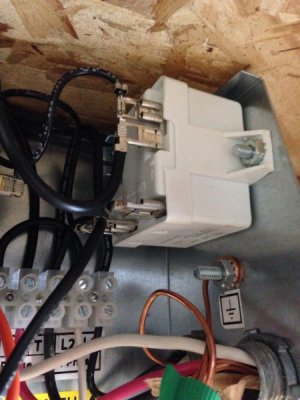
Second, if the static converter is making ANY sort of noise the potential relay they are using to control the start caps is not opening and the start caps are staying in the circuit. This WILL cause them to blow up. While I realize that there are a lot of manufactures out there that utilize potential relays for controlling start caps in a RPC it's not a good idea. It's cheaper and a better option to run a pushbutton start that controls the caps and then drops them out once you release the button.

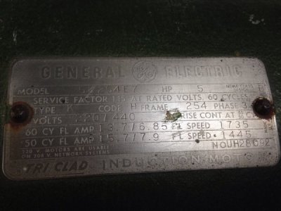
Post a full set of pics of the interior of the static so I can see what's in it and give you better direction. Also include a pic of the idler motor information plate.

I've been away from the shop and might not be back untill Friday but I will most certainly post pics of the whole system and a quick video of in use. I've logged about 20 or so hours on the system with nothing bad happening but will refrain from use untill I get some more info


Sent from my iPhone using Tapatalk
 
If you have run it that long and the caps are still intact, they are probably going to be fine, but if the box is making any sort of noise, that needs to be addressed. Personally I don't care much for using potential relays for start caps. The way they work is they are normally closed (connecting the start caps to the motor) and look for a certain voltage to develop between the created leg and one of the other two powered legs. Once the voltage hits the relays preset voltage it switches the caps out of the circuit. Now for a guy that is building one at his house, and knows what voltage is going to develop across the legs, they are viable. But depending on your electrical provider, your 220 power may be 225 or 230 and mine may be 222 or 220. So what you need and what I need are two different things but that's not typically addressed with a store bought unit. The other issue is that alot of builders will look at the start current of the motor from the name plate and install a relay that is rated for that value. We are not starting these idler motors on 3 phase which is what the name plate indicates. The start currents are higher with an idler motor and that puts more load in the potential relays contacts occasionally causeing them to weld together. This brings a quick and loud end to your start caps. It's why I use a high current contactor (60 amp typically) and a time delay relay that controls it. The other plus to this is if you have a unit with this design, and it doesn't quite fully start, you open the cabinet and adjust the relay adding time to the closed part of the cycle. That hold the start caps in longer and gets the motor fully started before taking them out of circuit.
 
OK, I went back and read your posts again. I see the issue. Your created leg voltage is LOW. Potential relays are designed for a voltage window to trip. My guess is that the window on yours is right at 208 on the bottom side and since you are at 212 / 208 loaded, it's chattering. That could very well be the noise you are hearing. I am going to assume that the cabinet has no run capacitors in it, or only has one run cap in it. This is done in cheap static converters because although they technically will work it's an additional 15 or 20 bucks for the builder to put one in. A good RPC will have 7-10 uF from L1 to L3 and 3-5 uF L2 to L3 per horsepower of the motor as labeled. For CNC type loads that are picky about their input power this may need to be tuned for the best voltage, but it's a good starting point. If you are only going to run a manual mill and/or lathe with no electronics other than BASIC control circuits (meaning no 3PH VFD's ) then you will be fine.

You still need to address the noise in the Static converter though. that's a problem that will get bigger and cause a serious headache.

Ok here's the setup.
IMG_2588.JPG
IMG_2589.JPG
IMG_2590.JPG
IMG_2591.JPG
Idler motor

Static and idle motor firing up

Mill(load) firing up

Static converter making its noise, it's decibel level isn't too high it's just kind of annoying.

I think everything is running as good as that static can be, assuming it's obviously of the cheaper models you speak of.

I'm comfortable enough with electricity and Internet research to build my own static portion, can't justify buying a new rpc for 6-700$ when I know most of that costs is for the idler motor which I already have that works fine.

Would love to hear your continued thoughts on what I have after seeing the photos and the videos.

Thanks


Sent from my iPhone using Tapatalk
 
Back
Top