Information Gathering For Cnc Control Box Wiring

davidh

Active User
Registered
Joined
Jan 23, 2012
Messages
1,216
i have the mechanical end of a cnc router / machine almost done, now i need to wire all the controls and electronic stuff in a enclosure. I'm looking for photos of others that have done these already. i don't want to reinvent the wheel unless i absolutely.
i have the components necessary but lack connectors to get all the wiring to and thru the wall of the enclosure. the breakout board is straight forward, just a fancy cutout but for the other 16 or so wires, I'm just not sure what i should use. major plug ? a couple major plugs ? one for each motor ? what kind would i need to look for ? i have many feet of small colored automotive wire, is this satisfactory or will this kind of wire pick up signals its not suppose to see ? shielded cable required for each motor ? terminal blocks inside the enclosure ? my brain starts to go crazy with all the variables here. please help if you have time.
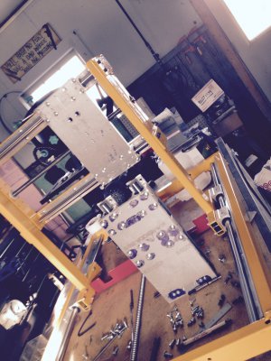
thanks much and Merry Christmas to all of youIMG_2343.jpg .
 
Wire to box connections would be dependent on conditions in use, if liberal flood coolant is employed then liquid tight fittings would be used, you don't want liquid coolant entering the control enclosure do you? If wood/laminate/plastics dust then there are 2 options, a filtered fan of suitable volume will raise the internal pressure above ambient pressure therefore the dust will not be able to enter, or liquid tight fittings. As far as physical wire connections use the most robust ones that you are willing to pay for.
As a side note, if said machine is expected to move for several million cycles (you built it and probably expect it to work for many years) use wire designed for this purpose, hardware store stranded building wire THHN/MTW for instance is not ideal for the moving parts.
 
I am by no means an expert on this subject but I will pass along what I learned from others on this forum. First a few pictures of my enclosure.

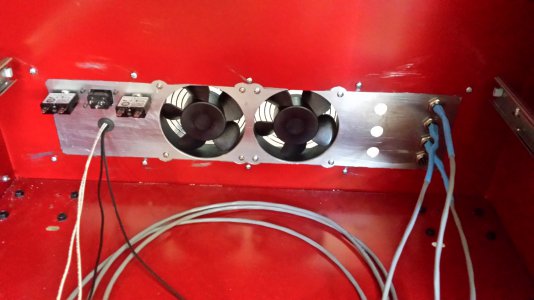
Here's a view of my not yet completed input panel. I have 120v and 220v AC power coming into my enclosure. 220v feeds the power supplies and 120v feeds the cooling fans and a dc wall wart power supply. There are two 15A 120v breakers (using one the other is a spare). The cables with blue shrink tubing are my motor leads. Note the fourth hole for the future installation of the A axis. The three holes to the left of the motor leads are for the limit switch cables. I used aircraft style plugs for the motor and limit switch cables.
20150301_084021.jpg

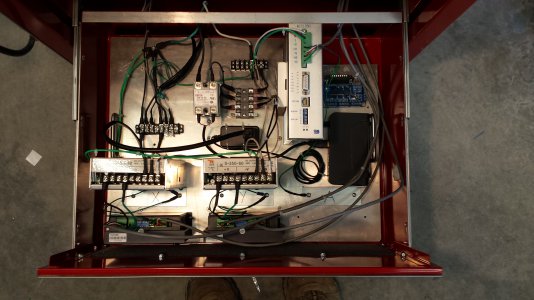
This picture shows the wiring about 90% done. All cables between the motors and drivers and between the drivers and power supplies are shielded as are the cables to the breakout board. Limit switch cables should also be shielded. I ran out of shielded cable and wanted to get my machine running so I used speaker wire with the intent of changing it at a later time. I haven't had any noise problems so still haven't switched it out. I have a DC/AC solid state relay powering up the power supplies. Each is protected with a fuse. Note the two terminal blocks. I separated the incoming 120v and 220v power. For the 120v and 220v circuits I recommend using wire that is rated for that voltage. Automotive wire is OK for the DC circuits but as I recall is rated 60 volts max.
20150409_154935.jpg

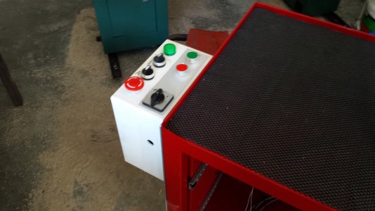
I moved my control panel from the mill head to the roll away that my enclosure is mounted in. My thought was I didn't want to reach towards the cutting tool to hit the E-stop. And it made for shorter wiring runs.
20150301_084048.jpg

This is a brief summary and not intended to be a complete description of what you need to do. Hopefully it gives you some ideas. I have more pictures if you want more detail.

There is also some very good information in the build threads by jumps4 and jbolt on this forum.

Tom S.
 
Motors should have shielded cables, feed back case if using encoders shielded, I used some db44 connectors on my AB drives, I also used plc terminal cards for all the i/O, between the drives and bob, they are nice case they mount on a din rail, same with my power supply. My relays also mount to din rail. Most the pro enclosures use through connectors, I wont, all my wires will come up through the bottom of the enclosure, through a slot. The most important thing is earthing all the components. Ground interference is nasty, I had it, until I went through and regrounded everything properly. Fwiw none of my step/dir wires are shielded cable, but they are routed away from any high voltage lines. (High voltage being 120/240ac, 24v DC power) remember to earth everything to the same earth, that's the earth on your main 120 or 240 input, the green wire, not to be confused with DC ground or negative..
One more thing, EARTH PROPERLY
 
yipes, im having problems with what you are saying. what is AB drives, and pic terminal cards ? and i/o between drives and bob ? what is a "bob" ? the din rail too, what is that ?
earthing ? meaning grounding i assume. no problem there, my enclousure is a fiberglass one, my power supply is from a computer, 110v in, all the proper output will come from it. . . i really do understand grounds for the 110vac. what also are step/dir wires ? im old and cannot readily understand the lingo, help please ?
 
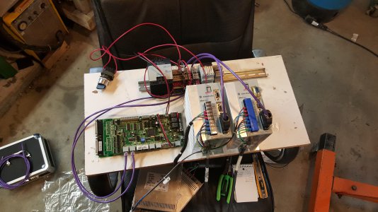
Step and direction is the signal coming from your breakout board "bob" to your motor drives, telling them how far to turn and which way. AB stood for Allen Bradley cause that's what I use. I/O is input/output, din rail is just a little metal rail made to din specs so that all kinds of parts will mount to it from different manufacturers. The PLC cards are input output cards, basically a terminal block, with an in side and an out side. Earthing is not to be confused with the negative DC Voltage referred to as ground. Totally different, smoke could ensue if mixed lol. Here's a pic of my breakout board and plc terminal cards, my AB drives, my AB power supply and AB relays mounted to a din rail.
20151020_141645.jpg
 
The signals for each drive step and direction go through the purple wires to the PLC terminal cards, then out to the drives along with some more signals.
 
And yes I would group wires into a plug for each motor and drive, easier to track down issues, and it's cleaner, mine are setup that way. Nice about using the PLC cards is that I have step dir and gnd coming from the breakout board into the cards, the ones I have are 4 terminal, there are 2 ins, and 2 outs on each card, I use I think 3 per motor, cause I have some other signals that have to go to the drives that don't come from the bob, so it makes it a clean way to have the output go into the same type 8 conductor purple wire as the input to the PLC cards. The drives themselves have db44 terminal for the inputs so I bought some connectors and soldered all the wires to it that are needed.
Another neat thing with the cards is that the 24v positive and negative, plus the 24v enable signal can all be cleanly Daisy chained over for each drive. Keeps it clean as to not have all these wires separate for each one of the drives
I also have a cool fuse terminal on the din rail that lights with an led if it blows, that's the 24v positive for my breakout board. You just flip a little lever to pull the fuse out. It helps keep everything compact. The big machines use plc type stuff like this. Some even have programable logic controllers "plc" to control tool changers and whatever
 
Last edited:
thank you very much. the picture is quite helpful. it appears my motors will want under 5 amps to run at what, 24-36 volts ? i found 4 and 6 pin bulkhead connectors that i would probably use thru the power case. i am also using a transformer / power supply from a computer that has the voltages i need. i also have two power supplies that are required for the 4 motor controllers. i guess one single one will not suffice. i think the motors are 425 oz or something close to that.
my electrical enclousure is a fiberglas box with two storys (two levels of plates to mount stuff) the top one being hinged to have access to the lower level. im assuming im going to need to install some metal grille stuff to let air in and heat out as there is also a clear plastic lid on the box thats hinged. and then also add some filter material to the inlet holes. the enclosure is pretty big but, it needs lots of stuff tucked into it besides somewhere in my little shop to put it. i have a cart that use to hold medical oxygen bottles for transporting around a airgas filling station that i intend to modify for the box and the dell computer and still have it under my work bench. i an out of space. nearly every horizontal surface has something on it, important or not, most of you folks will understand. i so wanted it to run today or tomorrow for demo purposes for the family gathering but, , , ,that was two months ago's hope, but life keeps getting in the way of the things i need to do to finish it. winter has finally reared its semi ugly head, snow plowing is required and maybe that will keep me around the farmstead more than when it was warm.
i also probably should put a couple fans in the box, eh ? its been a challenging but great project so far. even at nearly 74, im still learning new stuff daily. . . .thanks for your inputs. . .
 
I was waiting for chevydyl to explain his post before I chimed in. I didn't use PLC cards or din rails in my enclosure but that doesn't mean my enclosure is better than his. It just illustrates a different methodology, and there are many, of wiring up your electronics. You task is to gather information and decide what works best for you. Whatever approach you decide on we are here to help you through your build.

One thing to consider is whether you will move your mill and/or enclosure. If you have no plans to move either then you could hard wire your motor and limit switch cables rather than using bulkhead connectors. Going this route would eliminate a lot of soldering. It would also make troubleshooting easier should you have problems at start up. Something to ponder.

Tom S.
 
Back
Top