INFO WANTED on (Tachometer for under $25 dollars)

Hello Martin,
It's Great to hear from you. I was getting worried and was just about to send out Crocadile Dundee to find you :lmao: . I am so glad you reposted the pics and the drawing is fantastic.

I just received my sensors from Korea today & I received my tachometers from China yesterday. I will place one of these on my mill drill, and one on my lathe.

I am trying to fit in (and finish) these projects and a few others before my grandson is born (due on March 29th, but I beleive he will decide to come early). Then Grandma and Grandpa will be on baby holding duty & loving every minute of it. :))

Anyway, thanks so much for reposting the info and adding the drawing.


Bob
 
Hi Bob,
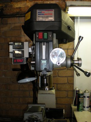
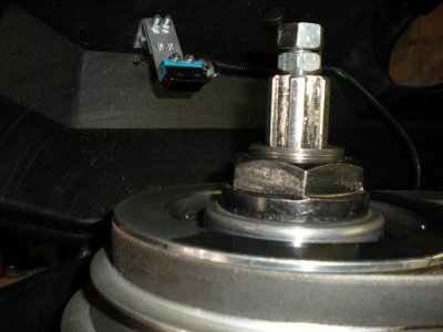
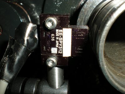
For a living I service Mail processing machinery, with billing cycles, the first and last weeks of the month are fairly busy. hence the delay in replying. I have also fitted a tacho to my RF 31 mill drill, it runs off a reflective sensor mounted to the under side of the belt cover looking at the spindle pulley which is polished and painted black for 50% of it's surface. the main reason for fitting it even though it has a fixed speed motor is that I am pretty lazy about changing belt speeds and it is a nagging reminder. If you let me know I will post some photos. I have the luxury of a 1 1/2 H.P. variable speed D.C. motor on my lathe and when I get my hands on another decent quality motor I will do the same to the RF 31.
Regards,
Martin
 
Martin,

My lathe is the same as yours. How much reflective tape do you have on the spindle , how long and how wide is the tape?
Did you pant the rest of the spindle black? If so, I presume it is a dull flat black, is that correct ?
If you can post the mill drill pictures I would like to see them. The casting on my mill drill had a few cracks on it. I just got it back from a frirend who welded it up. Now I need to clean it up, paint it and reassemble it.

Thanks,

Bob
 
Hi Bob,
The black on the spindle is just a wrap of black electrical tape, the reflective tape is about 15 x 30 mm. The sensor on the RF 31 is a Sick that was in the junkbox.
Regards,
Martinmt1.JPGmt2.JPG

mt1.JPG mt2.JPG
 
Martin, what is the distance you keep between the sensor and the spindle ?
When you turn on the lathe, does the tachometer have a quick response time ?

Are you sure of the value of the resistor RL being 1000 ohms ? I set mine up with reflective tape on the chuck of my drill press just to test it out . I held the sensor with my hand and I had very erratic readings . Does your tachometer always give the same values (or very close) if you turn on and off the spindle mutiple times.

Anyway, if you get a chance to give me a few answers, i would appreciate it.

Thanks,

Bob
 
G'Day Bob,
The spindle to sensor distance is about 3 mm, the load resistor could be replaced with a pot of say around 5 K ohms if you want play around with the load. My tacho stabilizes within about 2 seconds of start up and remains constant, when changing speeds the tacho responds and stabilizes within about 1 second. One of the guys down claims his was more stable after he fitted 4 reflective strips around the spindle and adjusted the multiplier to suit. Hope this helps,
Regards,
Martints1.JPG

ts1.JPG
 
Since things tend to get lost over time, I thought I better grab, edit, and archive the info on the digital tach itself - after realizing it had never been mentioned!

Measurement accuracy
0.1%±1digit / Special: 0.01‰ @ 25℃
Measure Range
0.15HZ—100KHZ
9r-999.99Kr/m
input signal
Signal Type
Dry contact、PNP、NPN、Pulse
amplitude 3-30V or 30-300V(High Voltage),this could be changed via adjust the Short circuit
Measurement Method
Full synchronization period measurement
Input Resistance
100KΩ
Power Supply
DC9-12V
Vibration Frequency :10-55HZ, Acceleration: 50m/s2
 X、Y、Z, each direction 5min X 10
Operating Temperature and Humidity
Temperature:-30℃-+70℃
Humidity: 25-85% RH
Panel Dimensions(mm) 79X43X25(L×W×H)
Cut-out Dimensions (mm ) 75X39.5


Function Selection:

• Frequency and Rotate speed display Set
(Please disconnect the input signal before setting when the input signal is High level voltage signal)
Open the back cover of the meter,
Press "S2" key to enter "SET" model and then press "S1" to change display mode,
"0" means Frequency display with filter ;
"1" means rotate speed with filter;
"2" means Frequency display without filter ;
"3" means rotate speed without filter.
10 seconds later, this meter will automatically return to the measurement mode, or power-off and restart, this meter still could return to measurement mode too.
• Divider Value Set
(Please disconnect the input signal before setting when the input signal is High level voltage signal)
Open the back cover, press the "S1" key to enter the Sub-frequency Value Set interface,"S1" key is the shift key, "S2" key is the value plus key, the divider value must be set in 1-99999 or 0.0001-9.9999 figures, and other value is invalid;After the set of the desired divider value via "S1" and "S2", wait 10 seconds and the meter will automatically return to the measurement mode, or power-off and then restart to return to the measurement mode .
Divider concept:
The number of the signal the gears get for one circle. For example, a gear can take 20 pulse signal for one circle , the divider value could be set to 20.
• High and Low voltage signal input switch
The default set for this meter is the low voltage input, if you need high-voltage input, you need to open the back cover the more the short jumper from the "L" part.
1: SIGNAL INPUT
2: SIGNAL GND
3: NC
4: INPUT VOLTAGE "-" : GND
5: INPUT VOLTAGE "+" : VCC
 
Down the road I might get a Tachulator from MKC Tools. Nice little setup and will do SFM or RPMs. It ain't under $25 but from all the reviews I've read it's a competent setup.

PS, forgot to say that I'm curious about the Arduino stuff and might build my own if I can find reliable plans. Anyone got any?

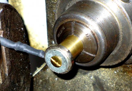
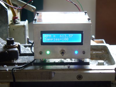
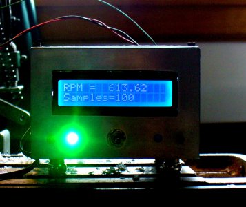
Are you interested in using an Arduino with a Hall Effect sensor as a tachometer? I've put together a prototype that seems to work although I haven't yet done a thorough job of checking it out. Also, I'm still experimenting with magnets and sensor positioning. I'm concerned about the reliability/repeatability, too. I use an LED that flashes when the Hall Effect sensor is triggered. That let's me position the sensor and get immediate feedback on whether it's reading pulses or not. P1160157.JPG P1160149.JPG The first photo shows a ring magnet on a brass rod. The sensor is to the left. This configuration doesn't work as well as some others I've tried. The second photo shows the LCD display. The green LED on the left is the power indicator. The Blue LED on the right indicates when pulses are received. I think typically tachometers allow a selectable period of time to elapse and count the pulses during that period. My approach is to count some number of pulses ("Samples" on the LCD) and then figure out how much time has elapsed. The switch on the box allows changing the number of samples. The default of 100 is okay for RPMs of 600 or more (for 600, it takes 6 seconds to get a valid reading) but for a rotation of 100 RPM, it would require a full minute and I thought this would be too slow. The switch allows changing the sample size in steps of 10 from a minimum of 20 to a whole bunch.

If this is interesting, let me know and I'll post my conclusions when I'm satisfied with the tach. I use the Arduino IDE and the program is in that format. The circuit is pretty simple and, except for the LCD and the Hall Effect Sensor, all the parts came out of my junk box.

P1160139.JPG P1160157.JPG P1160149.JPG
 
Back
Top