index marks at 120 degrees...A DUH moment.

tq60

H-M Supporter - Gold Member
H-M Supporter Gold Member
Joined
Jan 11, 2014
Messages
2,223
Today we were tinkering on a tool for working on Atmos clocks and we needed to make a drill guide to drill holes in a cup and mount.

The cup had a center hole and 3 mounting screws at 120 degrees and we do not have any rotary or index equipment and we were just building on ideas with no drawing.

We made a slug and faced it off then drilled a 0.625 center hole then turned the cutter in to cut a groove at 0.750 radius then was trying yo figure out a reliable way to index the face.

Did not need to be exact but wanted close.

The jaws were first thought and was thinking about a stick to register the chuck to the bed but did not have suitable item handy...lazy today but something else to make for next time.

Grabbed a level and leveled the jaw then used cutter to make scribe across the groove.

Was stupid simple and we got to thinking the 45 degree vial could add additional divisions....rough ones anyway.

Just thought we would share a simple discovery.
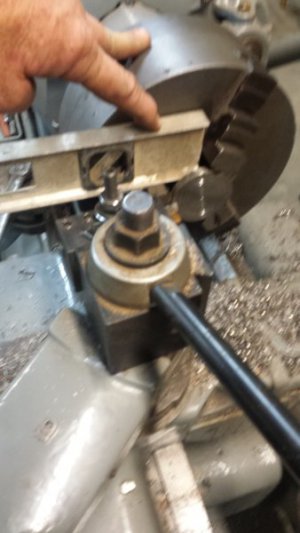
20171121_143023.jpg
 
Last edited:
What ever gets the job done, with what you have at hand. Thanks for sharing. Mike
 
I have done that myself a few times. Being sensible / realistic about the tolerances needed for a job can lead you to interesting solutions to a problem.

pete
 
Today we were tinkering on a tool for working on Atmos clocks and we needed to make a drill guide to drill holes in a cup and mount.

The cup had a center hole and 3 mounting screws at 120 degrees and we do not have any rotary or index equipment and we were just building on ideas with no drawing.

We made a slug and faced it off then drilled a 0.625 center hole then turned the cutter in to cut a groove at 0.750 radius then was trying yo figure out a reliable way to index the face.

Did not need to be exact but wanted close.

The jaws were first thought and was thinking about a stick to register the chuck to the bed but did not have suitable item handy...lazy today but something else to make for next time.

Grabbed a level and leveled the jaw then used cutter to make scribe across the groove.

Was stupid simple and we got to thinking the 45 degree vial could add additional divisions....rough ones anyway.

Just thought we would share a simple discovery.

Well done, You could double the number of divisions by setting the level on the jaws at the back of the lathe, so you would now have 6 x 60 deg.
 
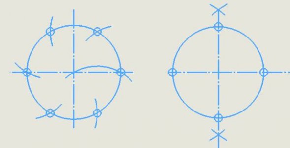
The traditional way of doing a divide by three is to scribe a circle with dividers and, without changing the dividers, mark out six equal divisions on the scribed circle. Then use every other mark.
 
The traditional way of doing a divide by three is to scribe a circle with dividers and, without changing the dividers, mark out six equal divisions on the scribed circle. Then use every other mark.

Can you explain in more detail? That does not make sense to me. If you use the radius to make 6 equal divisions of the circumference you will definitely be off since Pi is 3.14. Or do I misunderstand the method?

Robert
 
The circumference is Pi * diameter, but the RJSakowskis method is not about the circumference. It is marking the points of a regular hexagon where the length of the sides = the radius = distance between the points.

Try it on a piece of paper.
 
Back before CAD, when we made engineering drawings, we frequently had to construct our layouts. A six bolt hole pattern is easy which may be why it was used so often. Another which was four used was a four hole pattern. For a four hole pattern, the bp;t circle was scribed and the dividers set slightly larger. Thw first two diagonally opposite points werew chosen and intwersecting arc on either side from both of the first two point were scribed. A line through those points was drawn abd where they intersected the bolt circle marked the location of the second set of holes.
Bolt Hole Construction.JPG
 
Back
Top