- Joined
- Feb 5, 2015
- Messages
- 662
I'm posting this in the beginner's forum because I think this is where this procedure might be most useful.
Traditional adjustment of three-jaw chucks entails the use of a tool-post grinder. The jaws of the chuck are loaded at the diameter expected to be often used and then ground true. The following brief discussion describes a simple method that might improve chuck performance for the hobby machinist who lacks a tool-post grinder.
About thirty-five years ago I bought a used Austrian EMCO 8 x 18 lathe and spent a day aligning it: leveling the machine, adjusting the spindle bearings, aligning the tailstock, adjusting carriage/cross-slide/compound gibs … the usual process of setting up a small lathe. Concluding, I spent some time with the 3-jaw chuck, assuming that it would be the work-holder that I used most frequently.
(Note that this machine mounts the chuck directly to the lathe spindle and does not use a backplate. That's not common on American lathes.)
With a 1/2 diameter ground shaft secured in the chuck, run-out for the various combinations of mounting screw positions and chuck jaw positions (12 total combinations) was measured. This entailed rotating the chuck to each of the various mounting holes and moving the chuck jaws to each of the three different tee slots, measuring the run-out for every combination and recording it.
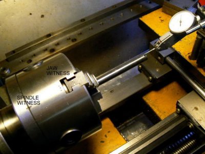
I found a combination that gave me .0005 runout and made witness marks on chuck and spindle flange with a center punch. Frankly, I don't recall how far away from the chuck jaws the DTI was placed for this measurement. I suspect that the measurement was adjacent to the chuck jaws and not three inches away as is shown in a photo below.
I also center-punched the three chuck jaws with one, two or three dots that corresponded to the same dots on the chuck body. The fit of the chuck to the spindle was a good one and I found no measurable difference in run-out when rotating the chuck with respect to the spindle - changing the mounting hole sequence - at least not using the .0005 DTI.
This may NOT always be the case however and it may be worthwhile to rotate the chuck on its backplate to find the most concentric location.
(For those concerned about subtle nuances of metrology, the "droop" of the measurement shaft due to gravity is negligible, being much smaller than the resolution of the DTI.)

Thirty-five years later, wear has degraded chuck run-out. A few months ago I measured run-out at .007 inches, three inches from the front of the chuck jaws with a similar 1/2 inch shaft as the one used for the initial measurement. I spent a very brief ten minutes moving the three chuck jaws to the two other possible locations in the chuck.
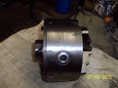
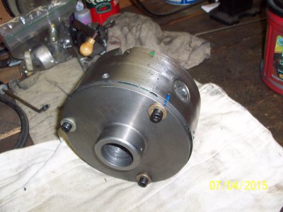
I didn't bother to rotate the chuck through the four different mounting hole combinations. Runout was reduced to .0025, three inches from the chuck jaws which made me VERY happy. It is visible in the above photos that the witness marks on the chuck jaws do NOT correspond with the original marks on the chuck tee-slots.
When performing an exercise like this, it's probably not useful to base the "best" configuration on the measurement of a single test rod (UNLESS the test rod is the diameter that you most often expect to turn). A better procedure might be to use three (or more) different work-piece diameters, moving the jaws through the various combinations to find the best for each diameter.
This can take hours and mentally "processing" the information might also take a while - be sure to record the results of the various combinations. The goal is to find the combination of jaw-to-chuck orientation that produces the least runout over the range of anticipated work-pieces.
The time will be well worthwhile if eccentricity can be improved by a factor of three which was the case described above. For the HSM, time is usually not a major consideration and a procedure like the one described produces benefits: the obvious one is enhanced concentricity of the three-jaw chuck.
It needs to be noted that a chuck with the provisions for mounting soft jaws is a better solution for accuracy. When a narrow range of diameters is being worked, soft jaws can be turned to an accuracy perhaps better than a collet, at least until wear degrades it.
"Set-True" chucks are also useful for achieving a high degree of concentricity and normally are capable of more operations of heavier work than soft jaws before adjustments are required.
Traditional adjustment of three-jaw chucks entails the use of a tool-post grinder. The jaws of the chuck are loaded at the diameter expected to be often used and then ground true. The following brief discussion describes a simple method that might improve chuck performance for the hobby machinist who lacks a tool-post grinder.
About thirty-five years ago I bought a used Austrian EMCO 8 x 18 lathe and spent a day aligning it: leveling the machine, adjusting the spindle bearings, aligning the tailstock, adjusting carriage/cross-slide/compound gibs … the usual process of setting up a small lathe. Concluding, I spent some time with the 3-jaw chuck, assuming that it would be the work-holder that I used most frequently.
(Note that this machine mounts the chuck directly to the lathe spindle and does not use a backplate. That's not common on American lathes.)
With a 1/2 diameter ground shaft secured in the chuck, run-out for the various combinations of mounting screw positions and chuck jaw positions (12 total combinations) was measured. This entailed rotating the chuck to each of the various mounting holes and moving the chuck jaws to each of the three different tee slots, measuring the run-out for every combination and recording it.
I found a combination that gave me .0005 runout and made witness marks on chuck and spindle flange with a center punch. Frankly, I don't recall how far away from the chuck jaws the DTI was placed for this measurement. I suspect that the measurement was adjacent to the chuck jaws and not three inches away as is shown in a photo below.
I also center-punched the three chuck jaws with one, two or three dots that corresponded to the same dots on the chuck body. The fit of the chuck to the spindle was a good one and I found no measurable difference in run-out when rotating the chuck with respect to the spindle - changing the mounting hole sequence - at least not using the .0005 DTI.
This may NOT always be the case however and it may be worthwhile to rotate the chuck on its backplate to find the most concentric location.
(For those concerned about subtle nuances of metrology, the "droop" of the measurement shaft due to gravity is negligible, being much smaller than the resolution of the DTI.)

Thirty-five years later, wear has degraded chuck run-out. A few months ago I measured run-out at .007 inches, three inches from the front of the chuck jaws with a similar 1/2 inch shaft as the one used for the initial measurement. I spent a very brief ten minutes moving the three chuck jaws to the two other possible locations in the chuck.
I didn't bother to rotate the chuck through the four different mounting hole combinations. Runout was reduced to .0025, three inches from the chuck jaws which made me VERY happy. It is visible in the above photos that the witness marks on the chuck jaws do NOT correspond with the original marks on the chuck tee-slots.
When performing an exercise like this, it's probably not useful to base the "best" configuration on the measurement of a single test rod (UNLESS the test rod is the diameter that you most often expect to turn). A better procedure might be to use three (or more) different work-piece diameters, moving the jaws through the various combinations to find the best for each diameter.
This can take hours and mentally "processing" the information might also take a while - be sure to record the results of the various combinations. The goal is to find the combination of jaw-to-chuck orientation that produces the least runout over the range of anticipated work-pieces.
The time will be well worthwhile if eccentricity can be improved by a factor of three which was the case described above. For the HSM, time is usually not a major consideration and a procedure like the one described produces benefits: the obvious one is enhanced concentricity of the three-jaw chuck.
It needs to be noted that a chuck with the provisions for mounting soft jaws is a better solution for accuracy. When a narrow range of diameters is being worked, soft jaws can be turned to an accuracy perhaps better than a collet, at least until wear degrades it.
"Set-True" chucks are also useful for achieving a high degree of concentricity and normally are capable of more operations of heavier work than soft jaws before adjustments are required.
Last edited:


