Adding i-Gaging DRO to my Sherline 4000 lathe
Adding DRO to my Sherline 4000 lathe
I recently became the owner of a Sherline lathe, 2 Unimat III lathes and tooling, and one Unimat III mill attachment through a series of trades. One of the first projects I wanted to attempt was to make one or all of these DRO at least and work towards CNC.I chose to add DRO to the Sherline first. It is a current production model and if I screwed up, sourcing replacements would be only a matter of how much I wanted to spend. After some email discussion, I purchased a 12” and 6” i-gaging DRO from member DAVIDH on this site and paid by PayPal. The package arrived promptly and gathered all the tools and bits I thought I might need.
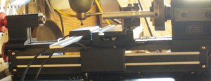
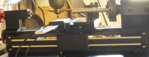
Step one was to decide placement of the X axis, after much tinkering I decided to mount it to the back of the lathe, taking care to be certain it tracked in parallel with the bed as it was attached to the cross slide. I was able to use an included bracket and existing 10-40 socket head screw on the cross slide to attach the Hall sensor. I used 10-40 coupling nuts (for threaded rod) to set the appropriate standoff from the sides. This works very well and for a bonus, it is practically unnoticeable.
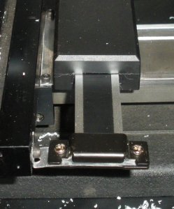
The Y axis is challenging with the i-Gaging scale and I have to say that while it works, I am working on other options. Scale placement is largely a function of where you can mount the sensor assembly. The only logical option seems to be placing the sensor in a fixed position top the base of the cross slide. I used aluminum flashing to make an attaching place. Tin snips work best for this – at least that was my conclusion after using aviation snips, Dremel, utility knife, and utility shears – all left the edge needing considerable work before it was safe for skin to slide past it and the Tin Snips left the cleanest edge. I attached the base of the sensor to the aluminum flashing with screws that came with the scales. I used 4-40 socket head screws on the cross slide after drilling and tapping three 4-40 holes, two for the sensor and one for the scale. The back side of the scale is free floating, I will trim and attach if accuracy becomes an issue. At this time, I would like to develop some experience before I cut. Another consideration is that if I mount the back of the scale to the table, then I have more to disassemble if I need to remove the table. As it is, I only need unscrew the one 4-40 screw. Incidentally, the 4-40 screws were ¼ inch long and I cut them to 1/8th inch. You can see the back of the slide in the photo above. Below is the top view:
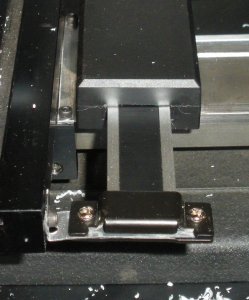
I am not totally happy with my workmanship on this as I believe I need to take the sensor off and file down the edge meeting the table as it seems to be making contact and dragging a little as well as the shade tree appearance. Since this is primarily a proof of concept and to check for repeatability, I will worry about finesse when I am satisfied with the function. Before I move to future changes and mention the little mistakes along the way, lets lake a quick look at the function of the DRO.
I was doing this in the living room and no, my wife was not happy about it. After mounting the Y axis and watching the display show the numbers as I moved it back and forth, I then reassembled the lathe and mounted it to the neat cabinet the previous owner built and carried it out to the workbench. The magnets on the readouts attached to the top of the workbench and I pulled an aluminum rod, cut off several inches and chucked it up. I cut the rod with my hacksaw (manual type) and it needed to be
faced. When I turned on the lathe, I was surprised to see how much the rod wobbled at the end. There was no way it was bent that much and I stopped the lathe and checked the chuck, the rod was secure with no wobble. I then tested the rod on a flat surface and it seemed to roll true. I decided to face off the hacksawn end and just that tiny bit removed trued out the rotation – It could not have been even a gram of weight removed.
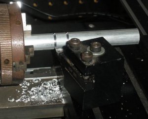
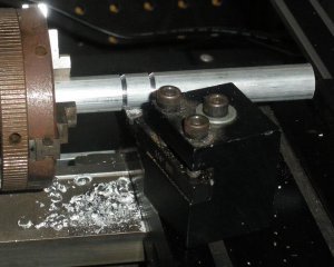
I then cranked out the tool until it just touched the rod and zeroed the Y, then I just chose a random point near the middle of the rod and cut 1mm in, I then cranked to zero on the Y and move the X 10mm and made another 1mm cut. After this, I stopped the work and pulled out my old slide calipers and measured shoulder of the cut to shoulder and it was exactly 10mm. Neat.
Here is a photo of that:
Here are the readouts attached to the workbench temporarily:

Future:
Now that I see that it works, my next step is to try a different approach to the Y axis, the i-Gaging DRO scale and sensor is just too large for the Sherline cross slide as a permanent solution. I have a digital caliper and I looked at using it here but the attached readout was not much better than the i-Gaging sensor although the scale was a better option. Also, the data port on the caliper had no schematic and was not a USB port either. Since it would not make me completely, I decided to keep the i-Gaging on the Y for now.
After reading on Yuriy’s blog, http://www.yuriystoys.com/2012/09/do...o-with-arduino- and.html , about adding DRO with Android and Arduino, I ordered the recommended kits and I also ordered hall sensors, a bipolar magnetic tape and other parts to see if I can make my own sensor and scale for the cross slide that will be unobtrusive and visually more appealing. I would like to attach the magnetic tape to the vertical side of the table and mount a miniature hall sensor assembly on the fixed portion of the slide. Ideally, if I could mill a channel in the base of the slide to fit the hall sensor, I would then attach the scale to the underside of the table and conceal all but the wires. It is a thought that I would like to play with. If that worked, it would be interesting to consider for the x axis.
I am looking into a cheap android tablet to replicate Yuriy’s project and then I want to add CNC driver and stepper motors as while the readouts are great, I do not have a feel for the machine. There is backlash and not every movement of the handwheels results in corresponding readout changes and I measured this – it was not the scales, it was the lathe. Looking into that. I am certain I can make adjustments to remove the play.
Mistakes:
I broke off the 4-40 tap on the third hole, luckily though a nipple was exposed and I was able to back it out with needle nose pliers. I should have removed the slide and table assembly then drilled and tapped the holes after careful measurement but I used the TLAR method and I should have sourced a helical tap as I did not make the holes through holes. Also, I tend to rush my work and am sometimes sloppy. I am not going to gloss that and say I prefer function to beauty, frankly I am impatient.
I recently became the owner of a Sherline lathe, 2 Unimat III lathes and tooling, and one Unimat III mill attachment through a series of trades. One of the first projects I wanted to attempt was to make one or all of these DRO at least and work towards CNC.I chose to add DRO to the Sherline first. It is a current production model and if I screwed up, sourcing replacements would be only a matter of how much I wanted to spend. After some email discussion, I purchased a 12” and 6” i-gaging DRO from member DAVIDH on this site and paid by PayPal. The package arrived promptly and gathered all the tools and bits I thought I might need.
Step one was to decide placement of the X axis, after much tinkering I decided to mount it to the back of the lathe, taking care to be certain it tracked in parallel with the bed as it was attached to the cross slide. I was able to use an included bracket and existing 10-40 socket head screw on the cross slide to attach the Hall sensor. I used 10-40 coupling nuts (for threaded rod) to set the appropriate standoff from the sides. This works very well and for a bonus, it is practically unnoticeable.

The Y axis is challenging with the i-Gaging scale and I have to say that while it works, I am working on other options. Scale placement is largely a function of where you can mount the sensor assembly. The only logical option seems to be placing the sensor in a fixed position top the base of the cross slide. I used aluminum flashing to make an attaching place. Tin snips work best for this – at least that was my conclusion after using aviation snips, Dremel, utility knife, and utility shears – all left the edge needing considerable work before it was safe for skin to slide past it and the Tin Snips left the cleanest edge. I attached the base of the sensor to the aluminum flashing with screws that came with the scales. I used 4-40 socket head screws on the cross slide after drilling and tapping three 4-40 holes, two for the sensor and one for the scale. The back side of the scale is free floating, I will trim and attach if accuracy becomes an issue. At this time, I would like to develop some experience before I cut. Another consideration is that if I mount the back of the scale to the table, then I have more to disassemble if I need to remove the table. As it is, I only need unscrew the one 4-40 screw. Incidentally, the 4-40 screws were ¼ inch long and I cut them to 1/8th inch. You can see the back of the slide in the photo above. Below is the top view:

I am not totally happy with my workmanship on this as I believe I need to take the sensor off and file down the edge meeting the table as it seems to be making contact and dragging a little as well as the shade tree appearance. Since this is primarily a proof of concept and to check for repeatability, I will worry about finesse when I am satisfied with the function. Before I move to future changes and mention the little mistakes along the way, lets lake a quick look at the function of the DRO.
I was doing this in the living room and no, my wife was not happy about it. After mounting the Y axis and watching the display show the numbers as I moved it back and forth, I then reassembled the lathe and mounted it to the neat cabinet the previous owner built and carried it out to the workbench. The magnets on the readouts attached to the top of the workbench and I pulled an aluminum rod, cut off several inches and chucked it up. I cut the rod with my hacksaw (manual type) and it needed to be
faced. When I turned on the lathe, I was surprised to see how much the rod wobbled at the end. There was no way it was bent that much and I stopped the lathe and checked the chuck, the rod was secure with no wobble. I then tested the rod on a flat surface and it seemed to roll true. I decided to face off the hacksawn end and just that tiny bit removed trued out the rotation – It could not have been even a gram of weight removed.
I then cranked out the tool until it just touched the rod and zeroed the Y, then I just chose a random point near the middle of the rod and cut 1mm in, I then cranked to zero on the Y and move the X 10mm and made another 1mm cut. After this, I stopped the work and pulled out my old slide calipers and measured shoulder of the cut to shoulder and it was exactly 10mm. Neat.
Here is a photo of that:

Here are the readouts attached to the workbench temporarily:
Future:
Now that I see that it works, my next step is to try a different approach to the Y axis, the i-Gaging DRO scale and sensor is just too large for the Sherline cross slide as a permanent solution. I have a digital caliper and I looked at using it here but the attached readout was not much better than the i-Gaging sensor although the scale was a better option. Also, the data port on the caliper had no schematic and was not a USB port either. Since it would not make me completely, I decided to keep the i-Gaging on the Y for now.
After reading on Yuriy’s blog, http://www.yuriystoys.com/2012/09/do...o-with-arduino- and.html , about adding DRO with Android and Arduino, I ordered the recommended kits and I also ordered hall sensors, a bipolar magnetic tape and other parts to see if I can make my own sensor and scale for the cross slide that will be unobtrusive and visually more appealing. I would like to attach the magnetic tape to the vertical side of the table and mount a miniature hall sensor assembly on the fixed portion of the slide. Ideally, if I could mill a channel in the base of the slide to fit the hall sensor, I would then attach the scale to the underside of the table and conceal all but the wires. It is a thought that I would like to play with. If that worked, it would be interesting to consider for the x axis.
I am looking into a cheap android tablet to replicate Yuriy’s project and then I want to add CNC driver and stepper motors as while the readouts are great, I do not have a feel for the machine. There is backlash and not every movement of the handwheels results in corresponding readout changes and I measured this – it was not the scales, it was the lathe. Looking into that. I am certain I can make adjustments to remove the play.
Mistakes:
I broke off the 4-40 tap on the third hole, luckily though a nipple was exposed and I was able to back it out with needle nose pliers. I should have removed the slide and table assembly then drilled and tapped the holes after careful measurement but I used the TLAR method and I should have sourced a helical tap as I did not make the holes through holes. Also, I tend to rush my work and am sometimes sloppy. I am not going to gloss that and say I prefer function to beauty, frankly I am impatient.


