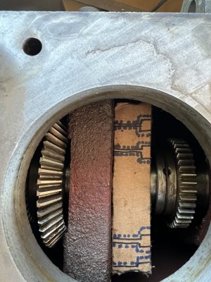
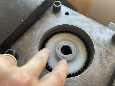
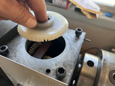
Well thank you for the thorough write up TQ 60. I think I smell what you’re getting at. If it is what I’m thinking, then I am limited to clearance on the top of the support with only about a 1/32” or less. I have attached a couple more photos showing why nothing can be attached to the top, which is why my drawing was showing the support attached to the front of the support. The bevel gear, which mates with the bevel gear you see in the top down picture is for the mill that attaches to the top of the head stock. this bevel gear sits almost touching the top of the bearing support(cracked piece). You can see that the portion that is cracked is very thin in section. Again, I think a very poor design leaving this area so thin.
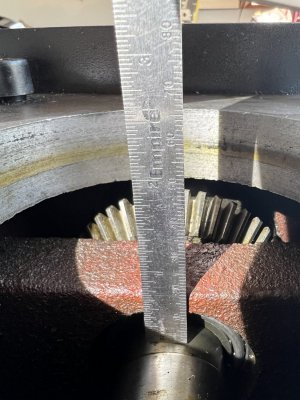
I am thinking with a plate of steel in front. I can still put some screws, parallel the spindle through the support into a piece of steel between the support and the chuck. The cracked portion is only about a quarter inch thick however I have 0.6 inches from the spindle to the top of the support. This allows me to use approximately 1/2 “ x 1” piece of steel. The steel will be placed in a strong access position so I should get maximum ridgidity out of it.
In order to do this, I will need to place a couple access holes through either the chuck side of the spindle or the opposite side to be able to run a drillbit through and a tap. I can then plug the holes with a threaded grub screw. If I only use 1/4”-28 bolts, then my access holes will only need to be about a quarter inch diameter and 46 of them should not weaken the structure substantially.
Attachments
Last edited: