

I've been ruminating on fitting the TX650 with a hydraulic clutch actuator for some time. Originally a plastic screw type actuator was fitted. The clutch action is a little heavy for my arthritic fingers and difficult to operate as my fingers are fused. At first I modified a spare screw actuator by lengthening the lever, it worked ok, but I'm not a fan of screw type actuators, so, I set about making a hydraulic actuator. I worked out I could fit a hydraulic slave to the inside of the side over with a max piston size of 25mm, requiring a master with a piston of around 10mm. That being the sticking point.
I finally found a master cylinder that 'should' do the job: Its for a KTM and has a 9.5mm piston. Its on order and should be here in a a couple of weeks, along with a couple of banjo fittings. Fitting the slave behind the cover seemed the best idea, as it provided a good solid stop against the clutch spring pressure and would be unobtrusive.
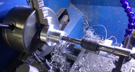
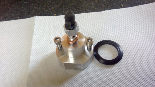
So, the last couple of days I've spent on the lathe and mill building a slave cylinder and modifying the side cover to fit it: Lots and lots of setting up to ensure the holes are in the right place and everything fits. Lots and lots of swearing and cursing as well.
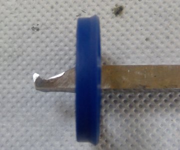
I've used a hydraulic ram seal to seal the slave, it has a slight lip on the side, so doesn't require a circlip to keep it from popping out.
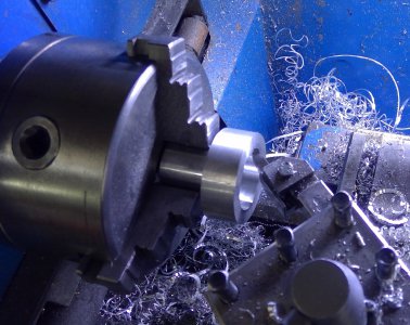
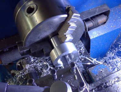
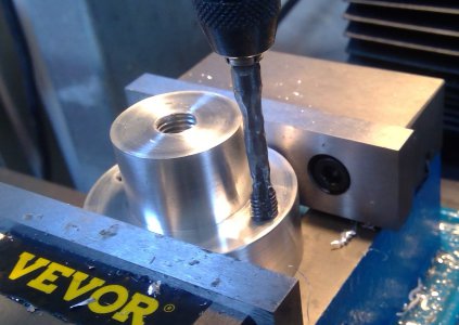
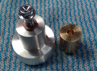
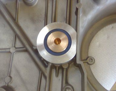
The piston is phosphor bronze, 25mm diameter and 28mm long, drilled 8mm to a depth of 20mm to take an 8mm ball and the 8mm push rod. Turning and milling the slave was a barrel of fun: I started with a small block of 50 mm 6061, faced it and bored it out to 25mm to a depth of 26mm, then enlarged the first 6mm to 33mm to take a hydraulic ram seal. The seal has a locating lip, so, I had to grind a tool to the ssame shape as the lip to turn a locating groove.
After the bore was done, I turned the slave around, chucked it and turned down the other end to 29mm for 18mm, drilled andbtapped a central hole 1omm x 1.25, then faced the end. I also had to mill 3mm off the 50 mm diameter end so it would fit in the side cover.
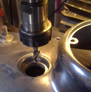
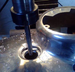
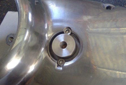
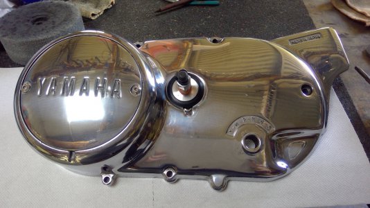
Once that was done, the engihe side cover was mounted on the mill and the 26.5mm screw actuating hole was bored out to 29 mm to fit the slave cylinder. The slave was fitted and the two mounting holes marked on the slave, then the slave mounting holes drilled and tapped to 6mm x 1.00 to a depth of 10mm, a mm or two short of the ram seal bore . The slave mounting holes on the the front of the side cover were then milled for clearance to take the allen screw heads.
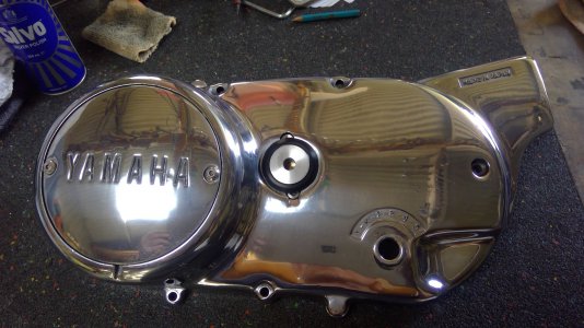
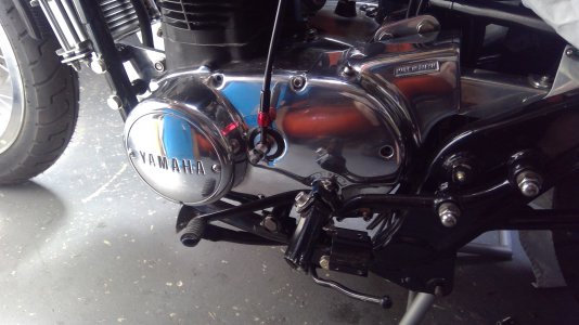
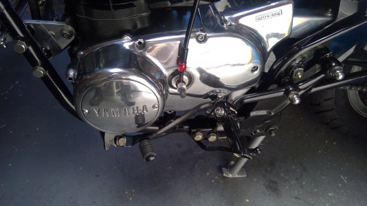
The slave is mounted where the original screw actuator sat, so space was tight. It's a rather dirty environment behind the cover, so I may have to fit a cover over the seal end to keep it clear of dirt and grease.
When fitted there is a rather largish gap between the slave and the cover recess, so I machined a pushmon Delrin ring to cover the gap.
Here's lots of pics of the build.
I finally found a master cylinder that 'should' do the job: Its for a KTM and has a 9.5mm piston. Its on order and should be here in a a couple of weeks, along with a couple of banjo fittings. Fitting the slave behind the cover seemed the best idea, as it provided a good solid stop against the clutch spring pressure and would be unobtrusive.
So, the last couple of days I've spent on the lathe and mill building a slave cylinder and modifying the side cover to fit it: Lots and lots of setting up to ensure the holes are in the right place and everything fits. Lots and lots of swearing and cursing as well.
I've used a hydraulic ram seal to seal the slave, it has a slight lip on the side, so doesn't require a circlip to keep it from popping out.
The piston is phosphor bronze, 25mm diameter and 28mm long, drilled 8mm to a depth of 20mm to take an 8mm ball and the 8mm push rod. Turning and milling the slave was a barrel of fun: I started with a small block of 50 mm 6061, faced it and bored it out to 25mm to a depth of 26mm, then enlarged the first 6mm to 33mm to take a hydraulic ram seal. The seal has a locating lip, so, I had to grind a tool to the ssame shape as the lip to turn a locating groove.
After the bore was done, I turned the slave around, chucked it and turned down the other end to 29mm for 18mm, drilled andbtapped a central hole 1omm x 1.25, then faced the end. I also had to mill 3mm off the 50 mm diameter end so it would fit in the side cover.
Once that was done, the engihe side cover was mounted on the mill and the 26.5mm screw actuating hole was bored out to 29 mm to fit the slave cylinder. The slave was fitted and the two mounting holes marked on the slave, then the slave mounting holes drilled and tapped to 6mm x 1.00 to a depth of 10mm, a mm or two short of the ram seal bore . The slave mounting holes on the the front of the side cover were then milled for clearance to take the allen screw heads.
The slave is mounted where the original screw actuator sat, so space was tight. It's a rather dirty environment behind the cover, so I may have to fit a cover over the seal end to keep it clear of dirt and grease.
When fitted there is a rather largish gap between the slave and the cover recess, so I machined a pushmon Delrin ring to cover the gap.
Here's lots of pics of the build.
Attachments
-
 427706335_3727835467476472_2539849298907454455_n.jpg629.3 KB · Views: 12
 -
 427690860_3727835540809798_1360653884843692257_n.jpg498.8 KB · Views: 10
 -
 427690103_3727835610809791_7601692126058521691_n.jpg503.4 KB · Views: 8
 -
 12.jpg305.6 KB · Views: 7
 -
 7.jpg293.1 KB · Views: 7
 -
 10.jpg258.8 KB · Views: 7
 -
 5.jpg265.9 KB · Views: 7
 -
 427719946_3727835667476452_53783969049367028_n.jpg505.1 KB · Views: 7
 -
 427719970_3727836137476405_5699239155948610571_n.jpg525.6 KB · Views: 8
 -
 14.jpg409.5 KB · Views: 7
 -
 13.jpg234.4 KB · Views: 8
 -
 428457174_3727836734143012_8215295837678667406_n.jpg569.2 KB · Views: 9
 -
 427696282_3727836887476330_2538648594566932249_n.jpg640.1 KB · Views: 11
 -
 427704946_3727836854143000_1667628728261849528_n.jpg481.3 KB · Views: 11
 -
 427719543_3727836844143001_8956329243921391577_n.jpg463.4 KB · Views: 13
