- Joined
- Feb 2, 2013
- Messages
- 3,957
I did a VFD and 3 phase 3 hp motor upgrade to my Shenwai 900B lathe, because i had a problem with the anemic single phase 1 hp single phase motor the lathe came with.
the issue was really evident when parting stainless. so much as to make me want to do the upgrade.
i wanted to use the original apron switch to operate the start and stop functions
i also set out to do it as inexpensively as possible as an added challenge
i chose the Huanyang 2.2KW inverter, $150
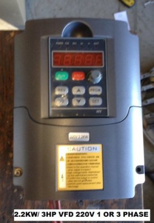
i chose a used salvage/surplus 3hp, 3 phase Dayton 56HZ frame 230/460 dual voltage 1740 rpm motor for the powerplant- i replaced the bearings in the motor with SKF bearings $80 total cost ($40 per bearing)
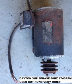
the problem was that the original motor was a metric frame motor with a 19mm shaft
the motor i intended to use had a 7/8" shaft.
56 frame motors usually have a 5/8" shaft.
the best recourse i could imagine was to bore and broach the pulley to fit the upgrade motor.
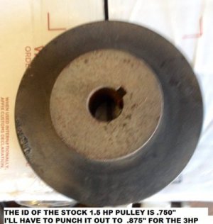
luckily i had a second lathe, a Hercus ARH 9" lathe to help out during the process.
i needed to bore the pulley but didnt want much deflection in a boring bar.
the stiffest bar i had was for a larger lathe, but i made some modifications to get over that hurdle...
i had to turn down a larger lantern toolpost to install into the Hercus compound rest
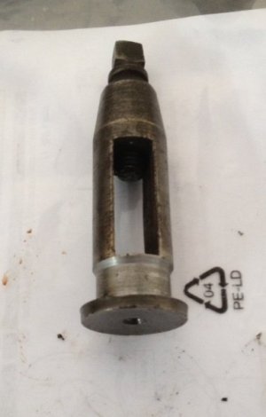
after that i could use the larger boring rig

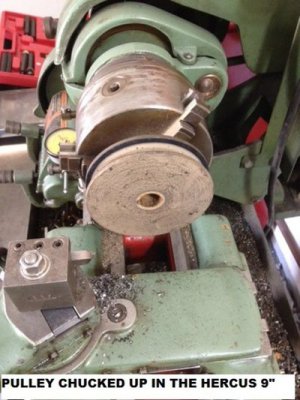
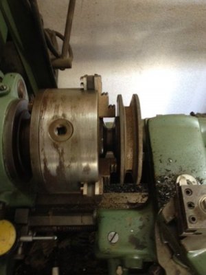
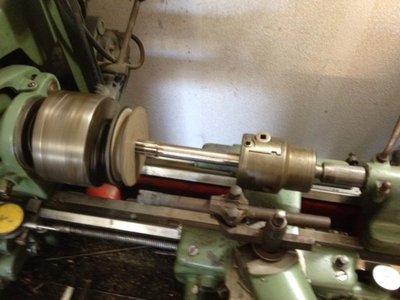
i drilled to 25/32", then bored the pulley to 13/16" and used a .7845" straight chucking reamer under backgear power to ream the bore to finished size
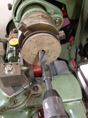
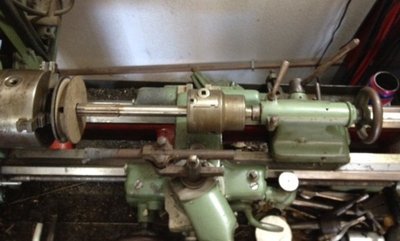
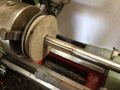
i held the 5/8" reamer shank in an indispensable, antique, Double Grip drill chuck in the tailstock
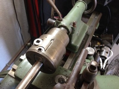
live action shot of the reaming operation,
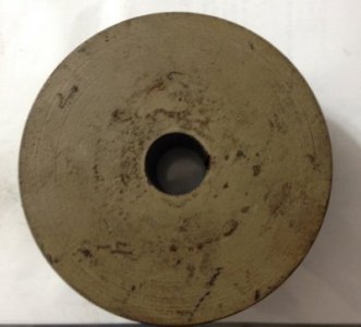
here is the finished bore
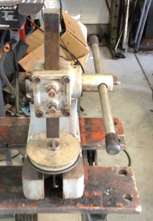
next is the broaching of the 3/16" keyway, and a test fit
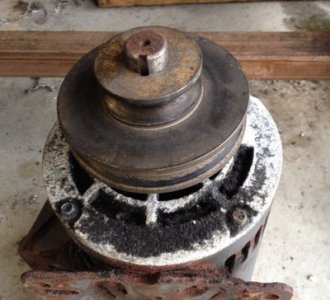
i installed the key and locked down the transverse lock screw too
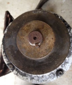
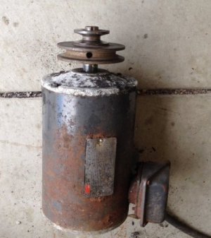
i then installed the motor into its nook
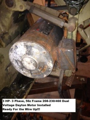
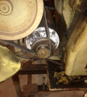
i replaced the belt with a B32 drive belt after the conversion, the belts were in poor shape.
i also added a salvage disconnect
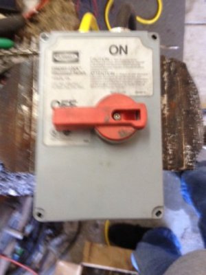
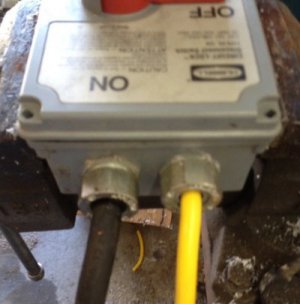
i wired the disconnect to the VFD, and from the VFD to the motor, then the VFD to the Apron Control Circuit
the project worked out like this...
150 inverter
80 bearings
10 miscellaneous hardware
85 miscellaneous electrical cord, connections and twist lock plug
20 belts
total estimated cost $350
i set the vfd up and wired it in and changed the VFD operational parameters to suit my needs.
i was able to wire in the original apron switch to operate the VFD's directional control.
i chose to use the operator potentiometer to set and adjust the frequency
i'm operating in the 0- 70 Hz frequency range and will use the pulleys to manually change between speeds outside that envelope.
for those interested, i made a video of the set up as well as my parameter selection for my motor.
if you have nothing better to do for the next 9:44, have a look
also for the interested is the parameters i set for the 3hp, 3 phase, 1740 rpm motor, as follows
PD001=1
PD002=1
PD003=60
PD004=60
PD005=70 (you can safely set up to 90)
PD008=240V (set you inverter to your tested supply voltage reading)
PD014=1.2
PD026=1
PD041=12
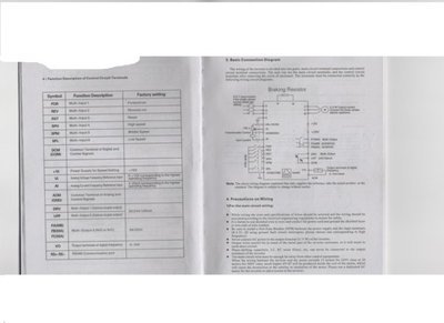
DCM is the supply voltage for the inverters multi input
i used the DCM power through my original apron switches to operate the VFD
the forward apron switch was connected to the FWD terminal of the inverter
the reverse apron switch was connected to the REV terminal of the inverter
as always thanks for looking, reading, and watching!
the issue was really evident when parting stainless. so much as to make me want to do the upgrade.
i wanted to use the original apron switch to operate the start and stop functions
i also set out to do it as inexpensively as possible as an added challenge
i chose the Huanyang 2.2KW inverter, $150

i chose a used salvage/surplus 3hp, 3 phase Dayton 56HZ frame 230/460 dual voltage 1740 rpm motor for the powerplant- i replaced the bearings in the motor with SKF bearings $80 total cost ($40 per bearing)

the problem was that the original motor was a metric frame motor with a 19mm shaft
the motor i intended to use had a 7/8" shaft.
56 frame motors usually have a 5/8" shaft.
the best recourse i could imagine was to bore and broach the pulley to fit the upgrade motor.

luckily i had a second lathe, a Hercus ARH 9" lathe to help out during the process.
i needed to bore the pulley but didnt want much deflection in a boring bar.
the stiffest bar i had was for a larger lathe, but i made some modifications to get over that hurdle...
i had to turn down a larger lantern toolpost to install into the Hercus compound rest

after that i could use the larger boring rig


i drilled to 25/32", then bored the pulley to 13/16" and used a .7845" straight chucking reamer under backgear power to ream the bore to finished size


i held the 5/8" reamer shank in an indispensable, antique, Double Grip drill chuck in the tailstock

live action shot of the reaming operation,

here is the finished bore

next is the broaching of the 3/16" keyway, and a test fit


i installed the key and locked down the transverse lock screw too


i then installed the motor into its nook


i replaced the belt with a B32 drive belt after the conversion, the belts were in poor shape.
i also added a salvage disconnect


i wired the disconnect to the VFD, and from the VFD to the motor, then the VFD to the Apron Control Circuit
the project worked out like this...
150 inverter
80 bearings
10 miscellaneous hardware
85 miscellaneous electrical cord, connections and twist lock plug
20 belts
total estimated cost $350
i set the vfd up and wired it in and changed the VFD operational parameters to suit my needs.
i was able to wire in the original apron switch to operate the VFD's directional control.
i chose to use the operator potentiometer to set and adjust the frequency
i'm operating in the 0- 70 Hz frequency range and will use the pulleys to manually change between speeds outside that envelope.
for those interested, i made a video of the set up as well as my parameter selection for my motor.
if you have nothing better to do for the next 9:44, have a look
also for the interested is the parameters i set for the 3hp, 3 phase, 1740 rpm motor, as follows
PD001=1
PD002=1
PD003=60
PD004=60
PD005=70 (you can safely set up to 90)
PD008=240V (set you inverter to your tested supply voltage reading)
PD014=1.2
PD026=1
PD041=12
DCM is the supply voltage for the inverters multi input
i used the DCM power through my original apron switches to operate the VFD
the forward apron switch was connected to the FWD terminal of the inverter
the reverse apron switch was connected to the REV terminal of the inverter

as always thanks for looking, reading, and watching!
Last edited:

