
I like the idea. Have heard about adjustable parallel but didn't think I need it until now. Will explore in that direction...... Use an adjustable parallel between your fence and workpiece.....

-
Welcome back Guest! Did you know you can mentor other members here at H-M? If not, please check out our Relaunch of Hobby Machinist Mentoring Program!
You are using an out of date browser. It may not display this or other websites correctly.
You should upgrade or use an alternative browser.
You should upgrade or use an alternative browser.
How to round a corner to a wanted radius ?
- Thread starter compact8
- Start date
- Joined
- Apr 29, 2019
- Messages
- 2,066
It depends on the needed radius, If the radius is small enough a corner rounding end mill is fast and easy but works best on square corners.
This is a part I had to make. It is .250 thick Stainless.
There are 3 outside radii and 2 inside radii all radii had to be tangent on both ends.
I then used a corner rounding end mill to put the nice radius all around the top edge.
This project sounds a lot like what you are doing.
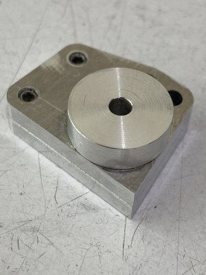
In this case I had to make 28 of them so I made a fixture that went into the #2 Morse taper in the center of my rotary table.
I did all of the calculations and layout in cad to design the fixture.
The fixture was a flat plate with 5 sets of mounting holes to mount the part. Each set of mounting holes would put the center of the radius exactly on the center of the RT. The mill DRO was zeroed on the center of the RT for the full process.
First OP was to cut blanks out of bar stock
Drill & C'Bore the bolt holes for a very tight fit on the screws so I could use them for locating on the fixture.
Drill and tap the center hole.
Flip the part and using the first set of holes as reference, drilled and C'Bore the 2 pockets for the O'Rings.
Back to the band saw to knock the 2 corners off so I had less stainless to turn into chips.
All of the outside profile was done with a 3/4 dia 2 flute indexable cutter, all of the rest of the work was HSS.
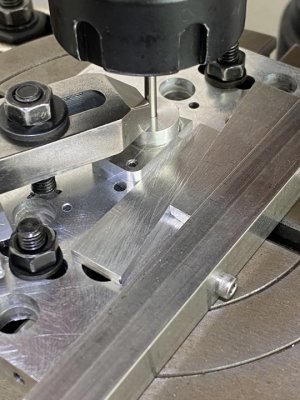
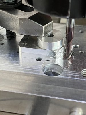
Then I had to mill one of the straight angled edges to the center of its R, rotate the RT to cut the first R, Remove the part and bolt it down to the next position, rotate the appropriate degrees and so forth till done.
Then came back and did it all again with the corner rounding end mill.
I then made a pass with the fly cutter to give it a nice look on the top surface. The tram was kicked very slightly "off" in the direction of cut to get just a semi circular pattern as the customer (ME) preferred that look to the pattern you get with the tram set perfect.
Last thing was to open up the bolt holes to a standard screw clearance.


This is a part I had to make. It is .250 thick Stainless.
There are 3 outside radii and 2 inside radii all radii had to be tangent on both ends.
I then used a corner rounding end mill to put the nice radius all around the top edge.
This project sounds a lot like what you are doing.
In this case I had to make 28 of them so I made a fixture that went into the #2 Morse taper in the center of my rotary table.
I did all of the calculations and layout in cad to design the fixture.
The fixture was a flat plate with 5 sets of mounting holes to mount the part. Each set of mounting holes would put the center of the radius exactly on the center of the RT. The mill DRO was zeroed on the center of the RT for the full process.
First OP was to cut blanks out of bar stock
Drill & C'Bore the bolt holes for a very tight fit on the screws so I could use them for locating on the fixture.
Drill and tap the center hole.
Flip the part and using the first set of holes as reference, drilled and C'Bore the 2 pockets for the O'Rings.
Back to the band saw to knock the 2 corners off so I had less stainless to turn into chips.
All of the outside profile was done with a 3/4 dia 2 flute indexable cutter, all of the rest of the work was HSS.
Then I had to mill one of the straight angled edges to the center of its R, rotate the RT to cut the first R, Remove the part and bolt it down to the next position, rotate the appropriate degrees and so forth till done.
Then came back and did it all again with the corner rounding end mill.
I then made a pass with the fly cutter to give it a nice look on the top surface. The tram was kicked very slightly "off" in the direction of cut to get just a semi circular pattern as the customer (ME) preferred that look to the pattern you get with the tram set perfect.
Last thing was to open up the bolt holes to a standard screw clearance.

- Joined
- Dec 12, 2016
- Messages
- 497
Joe Pi has a series of good videos on rotary table use and the geometry involved:
- Joined
- Nov 23, 2014
- Messages
- 2,607
Excellent videos by Joe Pi. I think the OP is asking how to setup his rotary table and subsequent work for cutting a radius.
First step is centering your rotary table on the mill's spindle. I'd start with a dial test indicator in the spindle with just the rotary table on the mill table. Turn the spindle by hand sweeping the DTI around the center opening of the rotary table (or around a pin in the center of the table). Zero out your hand wheels. Your rotary table is now centered on the mill's spindle.
Second step is centering your work's radius center point on the center of the rotary table. When you layout your project, you should know where the center of the radius is. Center punch it. Put a wiggler with a braille (sharp) point in the mill's spindle. Set your work on the rotary table and eyeball your center punched hole to close to center. Fire up your mill and true the braille point. Bring the wiggler point down into the center punched hole and retract it. If it's spinning off center, tap the work on the rotary table to better center it and repeat. Once you can lower/raise the wiggler into the center punched hole without the wiggler going off center, you've got your part's radius center point centered on the mill's spindle. Clamp down the work (best to have it lightly clamped to start with, then snug it down). Repeat the wiggler check to confirm nothing moved.
Now that the part's center is on the spindle/rotary table center, you can move the mill's table in X and/or Y to your radius dimension (plus the cutter's radius). You can also do this with an edge finder with a pointed end. The wiggler or edge finder are under $20.
If the tolerance only requires about +/- 0.010" accuracy, I'd use an SDA laser center finder (~$140 or around $40 occasionally off eBay). They make at least three variations of these: Center dot only, cross-hair and concentric circles with center dot. The circle one is really handy for getting within 0.010" (or better) of an existing hole or boss. Move the spindle up/down to change the size of the circle(s) to match your feature, then move the table until the circles line up. I'd use the laser to locate the rotary table center on the spindle's center. Set the work on the rotary table and move the work to pick up the work's radius center.
Bruce
Edge finder with a center finding tip

SDA laser/center edge finder

Doesn't show very well, but it's projecting circles on a dividing head indexing plate

Caveat on the laser is the line is wider than a scribe line. You can adjust the intensity to get a finer liner at the cost of visibility. I turn off the shop lights when using.

First step is centering your rotary table on the mill's spindle. I'd start with a dial test indicator in the spindle with just the rotary table on the mill table. Turn the spindle by hand sweeping the DTI around the center opening of the rotary table (or around a pin in the center of the table). Zero out your hand wheels. Your rotary table is now centered on the mill's spindle.
Second step is centering your work's radius center point on the center of the rotary table. When you layout your project, you should know where the center of the radius is. Center punch it. Put a wiggler with a braille (sharp) point in the mill's spindle. Set your work on the rotary table and eyeball your center punched hole to close to center. Fire up your mill and true the braille point. Bring the wiggler point down into the center punched hole and retract it. If it's spinning off center, tap the work on the rotary table to better center it and repeat. Once you can lower/raise the wiggler into the center punched hole without the wiggler going off center, you've got your part's radius center point centered on the mill's spindle. Clamp down the work (best to have it lightly clamped to start with, then snug it down). Repeat the wiggler check to confirm nothing moved.
Now that the part's center is on the spindle/rotary table center, you can move the mill's table in X and/or Y to your radius dimension (plus the cutter's radius). You can also do this with an edge finder with a pointed end. The wiggler or edge finder are under $20.
If the tolerance only requires about +/- 0.010" accuracy, I'd use an SDA laser center finder (~$140 or around $40 occasionally off eBay). They make at least three variations of these: Center dot only, cross-hair and concentric circles with center dot. The circle one is really handy for getting within 0.010" (or better) of an existing hole or boss. Move the spindle up/down to change the size of the circle(s) to match your feature, then move the table until the circles line up. I'd use the laser to locate the rotary table center on the spindle's center. Set the work on the rotary table and move the work to pick up the work's radius center.
Bruce
Edge finder with a center finding tip
SDA laser/center edge finder
Doesn't show very well, but it's projecting circles on a dividing head indexing plate
Caveat on the laser is the line is wider than a scribe line. You can adjust the intensity to get a finer liner at the cost of visibility. I turn off the shop lights when using.
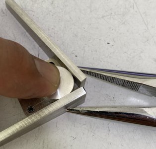
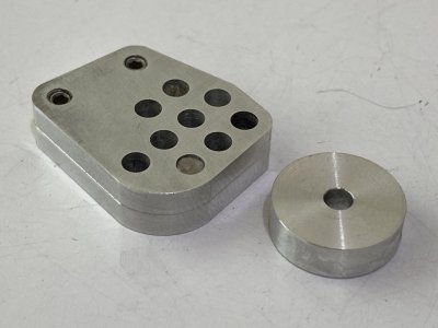
After tring varies methods, I found that having a hole on the workpiece at the center of the arc is the most convenient. At places where such holes are not available. Gluing one on works quite well. A thick washer of the wanted radius with a center hole is made. Then it is positioned over the workpiece as shown in the photo, super glue is sparingly applied to a few points along the base of the washer to hold it in place. The washer can be snapped off easily without heating after cutting is done.
Attachments
Last edited: