

-
Welcome back Guest! Did you know you can mentor other members here at H-M? If not, please check out our Relaunch of Hobby Machinist Mentoring Program!
You are using an out of date browser. It may not display this or other websites correctly.
You should upgrade or use an alternative browser.
You should upgrade or use an alternative browser.
How to measure and grind form tool.
- Thread starter FTlatheworks
- Start date
- Joined
- Oct 14, 2013
- Messages
- 997
Radius gouges are generally used with the Mark I eyeball to see how the part fits the curve. Sometimes you can sharpie the part and scrape the high spots with the gauge
Sent from my SM-S911U using Tapatalk
Sent from my SM-S911U using Tapatalk
John, last time I saw your CMM it was behind your lunar rover under a bunch of unobtainium. If not there then I apologize for not putting it back where I borrowed it from.Of course! By that, you mean setting a gauge pin in the groove and holding it up to the light, right?
I wish I could remember which drawer in my toolbox I put the temp controlled room and CMM in...
- Joined
- Jan 31, 2016
- Messages
- 11,488
I've got a set of Starretts here I'll let go reasonably priced just to get me started on this last job .I don’t even know how to use radius gauges yet. I’ll pick some up though.
- Joined
- Apr 23, 2013
- Messages
- 1,013
What size is the radius? What type material? How many do you need?
If you would like I will grind you one for free so you can have a template to go by.
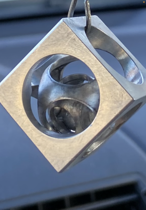
Picture is to show hand ground radius tools I made to make the balls in a cube.
email me if you would like a sample tool to work with. I just do this for a hobby.
jimatcf@hotmail.com
If you would like I will grind you one for free so you can have a template to go by.
Picture is to show hand ground radius tools I made to make the balls in a cube.
email me if you would like a sample tool to work with. I just do this for a hobby.
jimatcf@hotmail.com
Attachments
I have been making parts for a very large expensive machine at work. It looks like a mini pulley but it has a smooth radius instead of a v groove. I ground a tool by matching the shape of the part, but I know I didn’t do it correctly because I don’t have much experience. I can grind tools that work, but unless it’s a threading tool, I’m sure my angles and clearances are all off. The parts look and function ok and the tool gets the job done, but it’s by no means cutting efficiently.
Part of the problem with a form tool, is it cuts from a lot of sides. Top rake and side rake are most practicable to just leave at zero. In your case, with a tool presented horizontally, That means the top is just flat. There are options there, but the practicality of the matter says that you're either buying an insert (if one is available), or you're using a zero rake tool.
The clearance underneath... That looks a bit excessive. Something I'd do if I ware making a tool for my rocker holders, where the tool is presented at an upward angle. Ten degrees give or take would be plenty. I doubt that's bothering the tool's effectiveness or rigidity in this case, mostly it would go to cutting edge durability.
My questions are 1. How do you measure a part like this properly?
What degree of precision is required? In lieu of proper gauge pins (or an optical comparitor), if you've got a few thousandths to play with, how about the back of the drill bits in a 115 piece set? If you need a number, you can get pretty close, and interpolate between fits pretty accurately, again, depending on the precision required.
And in the end, it'll come to grinding a tool to whatever part you are able to measure, and then a test fit to look for daylight. There will be "some" if you're hand grinding, but you can get it pretty good. Also, depending on how the lathe is doing with a form cut that big, you might consider making the tool just a whisker (literally three or five thousandths) too narrow. Then set carriage stops, or put the compound in line with the axis, so that you can move the tool left and right by that same amount. That allows you to tease some metal out from one side, then the other, so you only engage half the tool (plus maybe a little extra at the very tip, so just a hair over half), versus burying the whole thing into one plunge cut. If you've got enough room in your tolerance to allow that "manually interpolated" bottom of the groove, it'll make the zero rake tool behave a lot better.
2. How do you calculate the angles and reliefs for the form tool?
Like I say, I wouldn't rake the top at all. If you do, one area gets more better, the other area gets more wrong. If you had a way to dish the top of that tool out like a tiny wooden spoon.... That might be useful. I've never figured out how to do that without spending more time, effort, and aggrivation than it takes to just gently coax a good but not optimal tool into behaving it's self for just a few minutes. The clearance angles underneath, those don't really need "calculating", they just need to be applied. There is some science to it, but realistically, you're looking at a real world useful range of something like 8 to 15 degrees. If in doubt, aiming for 10 and accepting one or two degrees either way from that is a pretty safe and workable solution in all but the rarest occasions.
The diameter of the part is only ,595. I made some out of hdpe to test my form tool, then made the rest out of aluminum. I’ve attached pictures below. I will post a picture of my parts (2 in plastic 1 in aluminum) then I will post the form tool and the original steel part.
You're already onto the best advice you'll get about ANY form tool. Test it. That's the final answer. All of the measurements, theory, calculations, and CNC grinding equipment in the world would sure be nice, but you've still got to test the tool in the real world before you call it good.
- Joined
- Apr 24, 2021
- Messages
- 462
I didn’t even measure. It would stop cutting after it got to a certain depth so I just kept giving it clearance. The other reason there’s so much clearance, I ruined the shape of the tool and the only way I thought to get it back with out starting over was to add clearance and reshape it.Lots of good info but one point I would make is the front clearance is far too much looks approx 45 deg ! it should be around 10/12deg. I appreciate you have stoned a very small area at the cutting point that may well be a smaller angle but I would grind it closer to a standard clearance angle, makes a better and stronger tool.
Also depends on the accuracy required but for many jobs comparison to a good set of radius gauges is just fine, if you need a rad that's not available just drill a hole in a piece sheet metal and cut the hole in half = a rad of you choice.
Hand grinding is an acquired skill and takes practise, a steady hand, well dressed wheel and a good eye, most of my tools are hand ground and back in the 60's it was the norm to grind your own tools unless it was a complex form tool.
A couple of picks of some of my tools made over the years -