How To Bore A Hole Which Is Off-axis, Using A Lathe

OldBeau44

Registered
Registered
Joined
Jun 11, 2015
Messages
5
This newbie has a question as first post. I am designing a future project, for a time when I have a lathe. I have searched the H-M site and did not find this discussed.

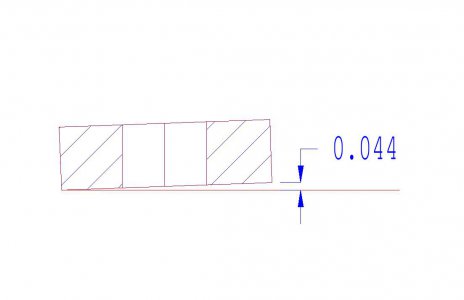
My project will require 32 - 0.5" shaft collars having the 0.5" hole at 2° off the axis of the two parallel faces of the collar, (see the sketch; if it is attached.) I hate to be totally ignorant, but my limited experience does not see a way to do this without a vertical mill, which may be more than I will be able to afford any time soon.

Could someone suggest if, and how, this hole might be machined using a lathe only? If it is possible to intentionally miss-align the collar in a 3-jaw chuck, it would require a 0.044" spacer on one of the three jaws, on the 1.25" OD of the collar, to create the 2°.

I appreciate all the time spent by those of you who are experienced, in order to educate those of us who are still trying to find the "ON" switch. My constant fear is that I will find and use the ON switch... before I learn how to put my brain in gear! :)
 

Attachments

  • Shaft Collar with angled hole-2B.pdf
    39.4 KB · Views: 105
That title should read:
"How To Bore A Hole
Which Is Off-axis,
Using A Lathe"
 
You could use a sine bar to come up with the angle. The question in my mind is whether you can firmly grip the work piece tilted. I would suggest using a 4 jaw chuck with jaws reversed, that is stepping down towards the center, you could place the work piece with one point laying on the face of a step(down in the jaw so you can still tighten it) then on the opposite jaw you would need a means of spacing it off the face of the step the distance that you would calculate using a sine. The other 2 jaws would simply grip the piece. Hope this makes sense.
Dave
 
My project will require 32 - 0.5" shaft collars having the 0.5" hole at 2° off the axis of the two parallel faces of the collar, (see the sketch; if it is attached.)
:)
For some of us, we are trying to figure out how not to do what you want!:laughing:

Seriously, with 32 of them to make, you might want to consider a custom fixture. Does the OD have to be perpendicular to the faces? Where is your angled hole centered, middle one face? What kind of tolerance on the location? You could face a piece with a two degree angle by shimming one side. An indicator and some trig will dial you in. From there, machine a bushing to fit over your OD and face it in the same manner. If the bushing is fastened to the plate and your part is inserted it will now sit at your 2 degree angle. Split the bushing with a hack saw and use a pair of vise grips to close it up and grip your If you have a drill press, the disks can be centerpunched and drilled. If you don't have a drill press, a shank could be fixed to the back of the plate and held in the tailstock with a drill in the lathe chuck.
 
This newbie has a question as first post. I am designing a future project, for a time when I have a lathe. I have searched the H-M site and did not find this discussed.

My project will require 32 - 0.5" shaft collars having the 0.5" hole at 2° off the axis of the two parallel faces of the collar, (see the sketch; if it is attached.) I hate to be totally ignorant, but my limited experience does not see a way to do this without a vertical mill, which may be more than I will be able to afford any time soon.

Could someone suggest if, and how, this hole might be machined using a lathe only? If it is possible to intentionally miss-align the collar in a 3-jaw chuck, it would require a 0.044" spacer on one of the three jaws, on the 1.25" OD of the collar, to create the 2°.

I appreciate all the time spent by those of you who are experienced, in order to educate those of us who are still trying to find the "ON" switch. My constant fear is that I will find and use the ON switch... before I learn how to put my brain in gear! :)
Use your four-jaw chuck. Put a cylindrical .044" shim behind the part on one jaw.
 
This newbie has a question as first post. I am designing a future project, for a time when I have a lathe. I have searched the H-M site and did not find this discussed.

My project will require 32 - 0.5" shaft collars having the 0.5" hole at 2° off the axis of the two parallel faces of the collar, (see the sketch; if it is attached.) I hate to be totally ignorant, but my limited experience does not see a way to do this without a vertical mill, which may be more than I will be able to afford any time soon.

Could someone suggest if, and how, this hole might be machined using a lathe only? If it is possible to intentionally miss-align the collar in a 3-jaw chuck, it would require a 0.044" spacer on one of the three jaws, on the 1.25" OD of the collar, to create the 2°.

I appreciate all the time spent by those of you who are experienced, in order to educate those of us who are still trying to find the "ON" switch. My constant fear is that I will find and use the ON switch... before I learn how to put my brain in gear! :)
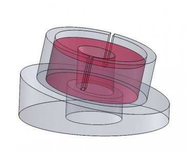
Dave, My previous post was slightly off. The bushing does not want to have a tapered face. This actually makes it easier. Here is a model of the fixture with one of your parts in red inserted. The model has a 10 degree angle instead of a 2 degree angle to exaggerate the illustration.
The plate can be made as previously described. The bushing would be made with a loose fit for your part the bushing would be aligned on the plate and tack welded to the plate. The assembled fixture could be mounted in the lathe chuck and a pipe clamp or u bolt clamp used to pull the bushing tight to your part. Mount a center drill in the tailstock and carefully spot the center then drill to size. You can use a hook to pull the finished part out or push it out with a bar through the spindle.

I hope this helps.

Bob
Angled Drill Fixture.JPG
 
I think the description might have been misinterpreted. If the degree angle is important I would make a holding fixture.

spacer.jpg
 
If the centerlines of both the OD and the ID have to coincide at one face then it's pretty easy. If, on the other hand, the intersection of the centerlines is midway through the part, you must comp for that with the fixture. Also this makes your OAL more critical. Same if the intersection lies outside the part, "in the air". It's all in the fixturing, which may be a lot of trouble to get right, but if you need to hold things closely, and there is a good qty, a fixture is the way to go.
 
Wow! Thanks gentlemen. I can see that it can be done, especially using a special fixture. Let me try to answer at least some of the questions...
First, a bit more info on the application. The 0.5" shaft does not rotate. Nor do the collars. The "shaft" is actually a curved section of 0.5" steel rod. Two of the collars hold between them, a 2" long X 0.75" OD straight tube, over the 0.5" rod. OAL of the collars is not critical.
1. Bob and Tony, your comments and questions made me stop and think about both the location of the common point of the centerlines, and the function of one collar face. Function demands that the two centerlines must intersect at one of the collar faces, because that face is going to be a bearing surface for an bronze thrust washer on the 0.75" tube. So that face must be perpendicular to the centerline of the straight 0.75" tube, but not necessarily at the center of the collar OD. So as Tony suggests, it should be pretty easy with a fixture like Bob's sketch.
2. Bob, I can see how the base of the fixture would be cut at the 2° angle, but I'm not clear on how you would accurately assemble the "bushing" to the slopped face of the base, and be certain of the location of the center of the hole to be drilled. Could you expand on this point?

Again, thanks to all.
Beau
 
Back
Top