How Do You Measure Groove Depth When Depth>width

tomw

Registered
Registered
Joined
Jan 24, 2015
Messages
239
Dear All,

I am cutting some piston grooves on a steam engine model. The are to be 0.054 +0 -.005 in depth, and 0.050 +/-.002 in width.

So, I cannot use my usual trick of measuring across something round of known size that sits in the groove (the groove is deeper than it is wide).

How would you go about confirming the depth of these grooves?

Thanks,

Tom
 
The standard way is to use a blade micrometer. Do you have a depth micrometer? Hard to say without knowing what you have on hand. Gage blocks? Need more info.

Width is easier with pins or blocks. Set up a go/no-go pair. Of course, there are instruments for that also.

In the "olden days" a pair of spring calipers and verniers would be used to get the "depth", or actually the groove diameter.
 
Tony,

Thank you for the rapid response. I have a 1" mic, 6" digital calipers, a set of gauge (or gage) blocks (but not two), height gauge, digital height gauge, and a surface block.

I had not heard of a blade micrometer. Neat and expensive. I guess I could machine a go/no go gauge on my mill, Say .049 by .053. If I take an outside mic reading and it is larger than the original diameter of the piston, I know I need to go deeper on the groove.

I wouldn't be so worried about this except for the tolerance call out on the plans. My original plan was to rely on my crossed dial.

Cheers,

Tom

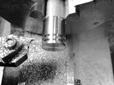
p.s Here is a picture of me making a trial piston. It is .508 dia x .250. The ring grooves are .05 by close to .054.
IMG_1578.jpg
 
Will the blades on your calipers reach to the bottom of the groove? If so put one blade in the groove and the other on the o.d. next to the groove on the opposite side of the piston and set zero. Then put both blades on the o.d. on opposite sides of the piston. The reading is the groove depth. The small error due to the blades not being quite opposite will be negligible.
 
On steam engines the depth you are searching for is only critical in considering the expansion of the ring material and the diameter of the piston in relation to the bore. You have the perfect set up in your picture, indicate the outside of the piston with your tool and trust the dial on your cross feed plus the allowed error of the print better to be deeper than too shallow. Good Luck. Andy
 
one way would be to turn up 2 parts that fit the micrometer anvil snug and having a .060 long diameter to fit grooves. Close micrometer to get initial reading with them on micrometer so you know how much to subtract from reading in groves.

another way would be to use a dial indicator with a tip turned down to .048 and set the indicator as close to center height of part as possible and check depth.
 
Andy, Thanks. That is the approach I have decided on. For future projects I am still interesting in hearing how folks to this.
Billh50, I like your idea of creating an blade micrometer. I might just try that!

Thanks,

Tom
 
Silverbullet, thread wire or other round things won't work because the depth of the groove is greater than the width.

Billh50, thank you for the links!
 
Back
Top