Holding a timing pulley to open bore

Usually the flanges have runout
Plus they are pretty flimsy and might collapse
In a 4 jaw chuck, the pulley can be made to run true regardless.

Taking light cuts it should be fine.

Sent from my SM-G781V using Tapatalk
 
Why knock off the flanges!

Hold the gear by them!

Just leave them in place, keeps the belt from wondering.

Sent from my SM-G781V using Tapatalk

Clamping on the pulley teeth will not always square up the pulley. I would glue the pulley's to a piece of round stock (faced and turned) using super glue and than put the package in the 4 jaw chuck to get the hole on center. When done, boil the 2 parts in water for half an hour to separate the parts or put them in an ultrasonic bath and some acetone.
Another good idea (the superglue trick). I've used that in milling aluminum and wood.
Clamping on the pulley teeth will not always square up the pulley. I would glue the pulley's to a piece of round stock (faced and turned) using super glue and than put the package in the 4 jaw chuck to get the hole on center. When done, boil the 2 parts in water for half an hour to separate the parts or put them in an ultrasonic bath and some acetone.

However, if the pulley teeth don't square up (regardless of what I'm holding them with, I can't imagine there's any fix I can make to resolve the problem. I'm pretty chicken about cutting a simple keyway, and there's no way I'm going to try to cut 40 new timing pulley teeth. But it's hard for me to imagine that the 4-jaw chuck won't be enough to adjust the pulley teeth on center. If the teeth are in a circle, that circle can be moved to swing around the center point of the spindle.
 
@rronald I like your idea. But it does seem like overkill. Something you could do more simply, while not dealing with the flanges, and keeping the teeth safe, is to use some 1/4” pine spacers between the part and the 4 jaws. Just a thought.
 
Maybe soft jaws for the 3 jaw. Bore to suit the gear and you have wide contact and zero runout.
IMG_1094.jpg

Greg
 
@rronald Personally, I really like your 3D-printed idea. If I were in your shoes, that is probably what I would do. You could certainly hold it with a piece of belting or pvc like the other guys have mentioned, but sometimes I like to geek out with my 3D printer (I have a Voron).

As you can see, there are quite a few ways to get this done, but you are on the right track.
 
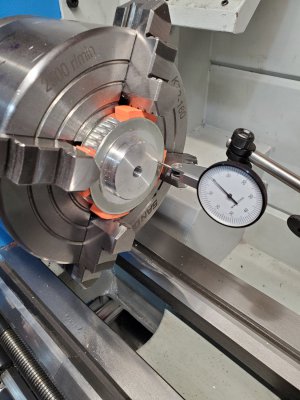
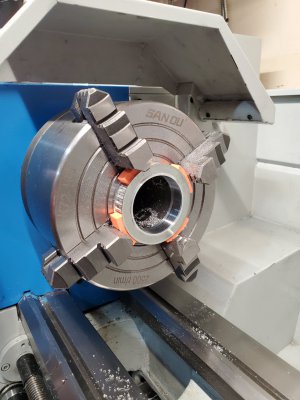
After reading everything suggested, I decide to go ahead with the 3d printed gripper quadrants, but decided to leave the flanges in place. Here are two pictures of the setup. It was easy to do, since my bore was just small enough that it fit thru the 4-jaw opening. That way, the pulley rested directly against the chuck and the piece seemed very secure. I indicated against he pilot bore and the raised boss. They were concentric with each other (+-.01mm)
20240103_092133.jpg20240103_114819.jpg
I have the hole bored to size. No problem doing that. However, I now need to do the keyway. But, the full height of the keyway is greater than the distance between the bore and the inner edge of the flange. You can see the edge of the flange in the picture with the opened bore, quite close to that bore. The flange appears a little less shiny in the picture. So if I cut the full keyway, the outer 1/2 of it will also need to remove part of the pressed on steel flange.

I see two options.
  1. Attempt to broach the keyway thru the side of the flanges and the pulley. I suspect that broaching thru the flange may push the flange off. It's not the end of the world if I lose one or both flanges.
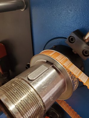
  2. The key for the shaft is quite large and constrains both the lathe motor v-belt pulley and this gear. The portion doing the v-belt has to handle a fair amount of power/torque. It doesn't need to be very large/strong for this timing gear (that only turns an encoder). I could grind the upper half of the key away (where it holds this gear) and make a shallow mating keyway in my gear. The other half of the key could remain full size for the motor pulley. In essence, I'd be grinding away about half the keyway for about half its length. Seems like this would still be plenty.
Even without a key, the encoder pulley will hold the torque to drive the encoder. Replace the long key by a short key and 3D print a filler to keep the key in place.
 
I did a keyway up to the flange. Ground down the key. And then used a triangle file to enlarge the keyway a bit more till I could get it in place. Probably could have just cut the key in half and not used any on this gear. The motor pulley acts as a substantial clamping mechanism that pushes the little pulley onto the shaft. Which results in this little pulley being squeezed into place.

Spindle gear.jpg
 
Last edited:
Why knock off the flanges!

Hold the gear by them!

Just leave them in place, keeps the belt from wondering.

Sent from my SM-G781V using Tapatalk
Thst likely will not work. Flanges are pressed on after the fact and I have yet to find one that runs true or even within 0.01 of true.
 
Back
Top