Help with rewiring an Emerson Bandsaw

porkchopxxx

Registered
Registered
Joined
Jan 20, 2017
Messages
6
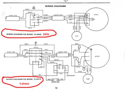
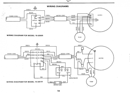
I just bought an Emerson Bandsaw off CL. It has a 3 phase motor and I'm going to switch it to a 120/240V motor. Emerson's 3 phase wiring diagram has me confused. I would have thought there would be 3 line wires, 1 neutral wire and a ground wire. There diagram show Black, Red, White & Green. With my limited electrical knowledge that seems weird. Like its 240V black & red are line, white is neutral & green is ground. What am I missing?

I want to try and use the original switches if possible. Any help would be appreciated.

Thanks,
Brandon
Screen Shot 2017-01-21 at 1.34.11 AM.png
 
What's the voltage of the pump motor? It looks like a three phase main motor - Black, red, white. White is used as a phase conductor in this application, Single phase is then tapped to the pump from the white and black phase. If your pump is the same voltage as the new main motor then just wire nut the red wire off at the main motor. Use only the red, black and green in the power cord. Connect the red to the top and middle terminal on the switch (you'll need to make a jumper wire) and the black to the bottom terminal. Make sure the motors and transformers are all connected for the new voltage. The transformer and pump might be 480v if this came from a large shop.
Looks like the top diagram might have two speed motor.
 
What due you mean about "phase conductor"? The top diagram is for the bandsaw offered with a 240v single phase motor and the bottom is for the 3 phase model. Even the top diagram is confusing to me. I thought current flows from the "line wire" to load (motor) through the neutral line. Ground is for safety ....

Shouldn't the top diagram have for the power cord:
black - line 1
red - line 2
white - neutral
green - ground

And shouldn't the 3 phase power cord have:
black - line 1
red - line 2
blue - line 3
white - neutral
green - ground


Screen Shot 2017-01-21 at 8.12.03 AM.png


Screen Shot 2017-01-21 at 1.34.11 AM.jpg

Is it possible to use the existing switch & transformer in a single phase application
If so what would be the connections for 240V and if possible 120V?
 
There won't be a Neutral. Only the three phase wires and ground will be there. I have seen the "white" wire used as a "hot" wire because the cord colors came that way. Looks like that is what was done. From the look of it, the pump motor is single phase and is connected "line to line". That can remain the same. If you go through with the conversion, you may be able to keep the wiring almost the same as the three phase one. You simply do not use one of the wires.

A couple of options. I'll talk about one of them.

Option 1: Not using Neutral for anything
You will need to be sure that the switch is rated for the single phase motor current. The single phase motor will likely draw more current per wire than the three phase one did. In the worst case you will need to make the switch larger. If the switch (actually it looks like that "switch" is a contactor on the three phase unit) is rated for the single phase motor current you can just disconnect and insulate the white wire. It will not be used. Don't connect it to the AC plug either. Insulate it there too. Be sure your source and motor are both 240 Volts (or 230 Volts...). The green wires are left alone. These are the safety ground wires.

Other options: Keep the three phase motor and get a phase converter or VFD. Use the Neutral wire to get 120V for accessories like a lamp. In any case, I suggest that you have someone that has some electrical experience, like an electrician friend check out your work.
 
If the neutral line is not used then doesn't the current flow through the ground wire? And if so couldn't you get a shock if you touch metal on the bandsaw?
 
In the US for almost all residences, the Neutral wire is used in the case where you need 120 Volts. The 240V is measured line to line and 120V from either line to Neutral. At your service panel, the ground (green or uninsulated) and neutral (white) are tied together. However, if your equipment does not need 120V, you don't need the Neutral. Current will not flow through the ground wire unless your equipment shorts out. The green wire is there to tie any metal parts of your machine to the grounding point back at your service panel. If any of the metal of the equipment comes into contact (shorts) with the live wires, a high current will flow through the ground wire and the wire that shorted to the metal for the brief time it takes for your circuit breaker or fuse to blow. That way the metal in this case, does not just sit there live ready to shock you if you touch it.

The green and neutral are tied together for a couple of reasons. One is that now any of your 120V outlets are only 120V "from ground" instead of possibly 240V "from ground". That means that less current (about half) flows through you if you touch the hot wire accidentally and another part of your body is grounded to something. By the way, the ONLY place the green and white wire should be tied together is back at the service panel, NOT at equipment or outlets or most anywhere else.
 
Oh, also, I agree with Jim18655. The main motor for the single phase model does look like a two speed one and you need to look at the motor voltages to make sure they are 230 or 240VAC rated. If you want a two speed setup, you will need the correct switch to allow you to switch high/Low/Off, and you will need a two speed motor. What is the horse power and voltage of the motor? If it is 240V and 3HP or less, you can use a VFD and get an adjustable speed very easily and roughly the same cost as the motor.
 
I canceled my order for the new 120/240v motor and I will get a VFD. Any recommendations for one?
 
I've had good luck with the GS series from Automation Direct for small motors. I have only purchased one for a 1/2HP and a 1HP motor from them. You will need to find one that can take single phase input and output three phase and large enough for your motor. What is your three phase motor horse power and voltage and the pump motor horse power and voltage? The motor details are generally on a nameplate on each motor. You will also need accessories for the drive. Fuses/Fuse holder, on/off switch or buttons, wire, etc. I would also put a line inductor in series with the motor. That helps the older motors if they are not rated for VFD. The pump motor should probably have its own switch and be driven directly from the 240VAC as it is now. The contactor will need to be rewired too. The motor details will drive which VFD you need.
 
The motor is a 2hp 1725 rpm 3 phase
Not sure on the pump (don't have the saw here) but I would guess a very minute draw. In a pinch I could wire up the pump independently with its own switch too.
 
Back
Top