- Joined
- Apr 24, 2021
- Messages
- 462
I bought a book about making percussion pistol or rifle. I plan to make a single barrel percussion cap shotgun first, then try to make a double barrel shotgun for birds and clay.
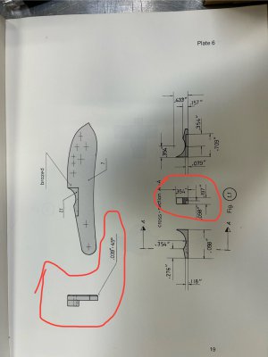
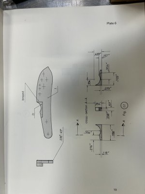
I have made my lockplate, but I can’t seem to figure out how this bolster should look. The drawing seems to completely over complicate the part. Can anyone tell me what some of these cross sections are signifying. I will circle them on a picture below. If someone could please explain it clearly to me, I would greatly appreciate it.
I have made my lockplate, but I can’t seem to figure out how this bolster should look. The drawing seems to completely over complicate the part. Can anyone tell me what some of these cross sections are signifying. I will circle them on a picture below. If someone could please explain it clearly to me, I would greatly appreciate it.