Having trouble after QCTP install.

I am not certain the bar ever ran true, this is a new to me lathe. Before, I was learning to thread but I was using very short pieces of stock. These same pieces of stock now seem out of round. I did make certain to clean the spindle threads very well both inside and outside threads. I believe we are on to something with the method in which I am tightening the saddle to the ways, maybe something is missing?? I looked over the parts breakdown, and think I may have determined the proper tightening points but those are bottomed out and doing nothing. I will have to look deeper into it when I get back in town later this week. TO answer your questions:

I am turning down 1.25" mild steel rod (cold roll?)
The tool bits are both HSS and carbide
The speeds I have tried are 350-700 RPM my feed is set to .011? and the DOC has varried but .002 to .0010
I have tried several tools, made new ETC with no luck. I thought the same thing.


Thank you for the help,

Jason
 
Did I miss something? What kind of a lathe is this? New, Used, Brand, Size e.g. 10-24 etc. Pics of the lathe, saddle etc might also help.
 
All or any of the above mentioned issues could be causing your problem.

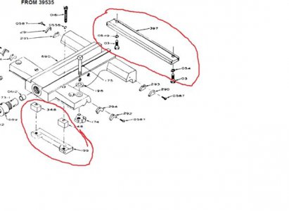
I was just going to mention the 4 screws/bolts on the saddle that tighten the saddle gibs ... but I think you may have found them. If not they are in red below. I think you lathe is the earlier version (if I remember correctly) but they are still there, and more easily visible in this parts breakdown. The front is up inside the bed and the rear is visible from the outside of the bed. If the saddle has been off, those spacer blocks can be a bugger to get back in place correctly. If I recall correctly, mine had a step in them and getting that step miss aligned created slop even if the screws were tight.
Untitled.jpg
 
I was going to post a picture of my saddle, but Mr Ed did me one better by posting the parts diagram. The carriage lock bolt that I was referring to earlier is part #175.
 
Since you were able to turn without chatter previously, it would seem to me that the cause of your chatter is connected with the tool post change. You said that you used your four jaw chuck to make the Tee nut which required removing and then reinstalling the three jaw chuck. Runout on a chuck will not normally cause chatter. A loose chuck will though. Mount a long sturdy bar in the chuck and see if you can detect movement when you push and pull on it. A dial indicator or rest indicator will make this easier. Push on the bar and note the indicator reading when you release the bar. Now pull on the bar. If the indicator reading changes, you have something loose in the chuck system.

If the chuck seems solid, the next possibility is the new tool post. You can run a similar test on the QCTP. If it appears solid then you will need to look elsewhere. I would suggest geometry. How are you setting your tool height? The wrong height will cause chatter. Are your tools mounted firmly in your new setup? You can always reinstall the old tool post to see if the problem goes away. This will narrow the possibilities.
 
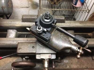
How about posting a photograph of your carriage, compound and tool post. If you just switched from a lantern type tool post to a QCTP, you may not know that there are about four right ways to set them and an infinite number of wrong ways. Also, if you are trying to use a cutter that was ground for a typical lantern setup where the top of the cutter blank is not horizontal, that cutter won't work right in a QCTP where the blanks are always horizontal.

Part bubble numbers 199 and 307 (or 397) are carriage hold downs (and there is no carriage gib on a V-bed carriage). This shouldn't have anything to do with your chatter, but with the carriage lock loose (as it should be for any operation involving carriage left-right movement), pick up on the apron. If there is appreciable vertical movement, there is wear on the top of 199. Same comment with 307 when lifting the rear of the saddle.The parts list does not show any shims so you might be able to reduce the front lift-off by removing 199 and the two spacer blocks and inverting 199 to get a new surface. From the drawing, I can't tell whether or not you can do that with 307.
 
I am not certain the bar ever ran true

........but if you cut the surface off once, that would true it.

New stock bar may not be round, especially near the ends where it is sheared. The first cuts may be "interrupted cuts" where you do not cut the entire surface because it is out of round. Typically it gets centred "close enough" and then once you make a pass that cleans up the entire surface. Now it is round.

Once that is done, (and if the work is tight in the chuck) then removing and replacing the chuck should not matter as long as the thread and shoulder are clean. The work should run true again. If that's not happening then the issue may be the chuck, or whatever reference your measuring the run-out from may be moving.

-brino
Thank you again for the information. I will double check the threads on the spindle and chuck. I am definately NOT centered, I am not concerned with the measuring reference moving as you can see it wobble! Something is definately not right!

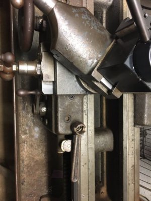
I took a couple pictures of the compound for reference. I can definately move the saddle up and down when the saddle lock is loose quite a bit, not .001 more like and 1/8"! I think you guys have figured out the problem, when I first brought the lathe home I had a machinist buddy look it over, he said everything looked good and helped me tighten up the gibs on everything, we used the saddle lock to tighten the front gib just because we didnt know any better and it seems to do the job. When I get home from my work trip I will try to figure out why I cannot tighten the front gib up to the underside of the ways up front. Looking underneath I can see about an eighth of an inch gap between the frame under the ways and the gib, I only know its the gib because if I loosen the two center bolts it gets looser, cant take the gap up but I can make it larger. What all is involved if I need to detach the apron from the saddle to get access to that gib?

Thank you again for all the very helpful responses!
image1.JPG image3.JPG image2.JPG
 
Last edited by a moderator:
One last thing, the unit has DEFINATELY been apart! I know this because I got a box of parts and tools with the machine and in that box was a set of half nuts that had been recently replaced. Thanks again, love a place with knowledgable people!

Jason
 
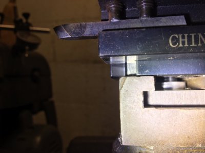
What did you have for your old tool post? The second photo shows what appears to be a negative rake on the top surface. This will work with a lantern type tool post as they angle the cutting tool up so you would end up with a zero or negative rake. Aloris type QCTP presents the tool horizontally so typically, the top of the cutting tool will be parallel to the shank or ground to provide a positive rake. A negative rake is essentially a drag type cut or scraping. Increased forces associated with negative rake tooling will expose issues with machine and/or workpiece rigidity which will cause chatter.
 
Back
Top