Greg's French 75 Mm Field Artillery Model

gjmontll

Active User
H-M Supporter - Silver Member
Joined
Nov 5, 2012
Messages
296
Upon my retirement two years ago, my first major project was to restore a 75 year old Logan 820 lathe. (See my "Greg's Logan 820 Restoration" thread.) While working this, several friends asked what I'd actually make with the lathe (and my X2 mill). I had some ideas, but nothing was firm.
Okay, after months of research, here's the planned project: create a detailed, scratch-built, scale model of the French 75 mm cannon, Model 1897. Three motivating factors:
  1. It's currently the centennial of WW I. Note: the first American shots were not fired until 23 October 1917, so I have 30 months to that precise 100th anniversary.
  2. Those historic first shots were fired by Battery C of the 6th Field Artillery. This was my grandfather's gun battery! So this project is in his honor. .
  3. Given my machine-shop hobby,it's ideal topic, requiring research, design, prototyping, creation and assembly of numerous metal (and wooden) parts. [My grandfather loved working in his shop too, mainly woodworking. I'll be thinking of him, particularly while making the spoked wooden wheels.]
Why did the Americans use a French cannon? Apparently it was better than what we had available.With a unique recoil absorbing mechanism, it didn't need to be manhandled back into position for each shot allowing a "high" rate of fire. The US took the design and built them during and after the war, designating them the M1897 and several followup models.

First major challenge is getting accurate dimensions of the numerous parts.
Last week I visited the Camp Roberts Historical Museum, in central California, to see their M1897 hoping to get virtually all the measurements I needed. Unfortunately, their gun is a later version, a significantly-different M1897A3. And it was missing several important assemblies. I did get a better understanding of the breech mechanism, and a few useful dimensions. (My grandfather's history-making gun is in the museum at West Point.)

The Ordinance Department's Handbook of Artillery has some un-dimensioned drawings, but they do have a scale bar. So I shall to use dividers to extract the necessary dimensions on major pieces. Then the undimensioned drawings in the US Army tech manuals, TM-305 and TM-1305, and a French document will used to get the required dimensional details.

I also have a contact in France who had attempted a similar project. He gave me the contact info another Frenchman who did the cannon in Solidworks. Maybe he will share them with me? [Interestingly, all three of us just happen to be ham radio guys.]

I'll use TurboCAD to first document the full-size gun, then to design the scale model. (I need to quickly get way more proficient with TurboCAD!)

My model will be between somewhere between 1:10 and 1:5 scale. It is not intended to be an firing weapon, but I hope to have as many of the mechanisms operable as possible. These may include the wheels, brakes, elevation and train mechanisms, recoil assembly, and the breech/ejector/safety/firing assembly.

I look forward to sharing my progress and problems with y'all.
 
Now that I've figured how to work our forum's new software to load pictures, here are a few images of the actual French 75 mm Modele 1897 that I am attempting to model.


And finally, the M1897A3, that I saw last week at the Camp Roberts Historical Museum, at San Miguel, California. The "gun" itself is quite similar, but the "carriage" is significantly difference.
 
that looks a whole lot like one on rodriguez range at camp perry ohio
 
So, it's been two months since I started this cannon project. What's been happening?
As I said in the initial posting, my first priority was to learn enough CAD to make some drawings. And then to extract/derive/estimate/... dimensions from some old American and French on-line documents. Here's a status update...

Climbing the CAD learning curve
In the 7 years or so that I've been doing home machining, I've tried a few different free or low-cost CAD packages on my home computer. I seem to have settled on TurboCAD, now have the Deluxe 2015 version. Over the past two months, I've struggled up the learning curve to the point that I think I can start the design work. I didn't fully appreciate the pros and cons of 2D vs 3D; [and still don't]. But I figured that since this was a very 3D project, I'd needed to be focusing making 3D objects in the CAD. Now it seems that while 3D must have its place, it doesn't work as well for making the fully-dimensioned engineering drawings one wants for machining. So, my focus is back on 2D and I've finally figured out enough to draw and print multi-view, dimensioned drawings.

Finding the Dimensions
My best resource for getting dimensions is Handbook of Artillery (HoA), USA War Office, Ordinance Dept, Wash. DC 1920. It has a table of a few useful dimensions, e.g. barrel length, wheel diam and track width, and a few drawings that have a scale bar, accurate to +`- 5 mm. With these I have extracted some initial key dimensions that I can use to determine the scale of other, more detailed drawings in this HoA and other documents, such as the Croquis du Canon de 75 Mle 1897, [French Artillery School]. It has good colorized detail drawings, but no dimensions. So I am determining the scale of its drawings as I go, as well as Google Translate-ing its component labels. (I do speak some French, but certainly not a technical vocabulary.)

The Question of Model Scale
How big will my model be? I had guessed something between 1:10 and 1:5 scale. I want it as big as my current machine shop will allow and think the 25/32" spindle bore on my Logan 820 lathe will be the limiting factor. And this limit will be in the drilling (and boring?) of the barrel. At a 1:8 scale, the barrel will be 12.795" long, with a muzzle diameter of 0.565 and a breech diameter of 0.787. That latter number is 6 thou too big to fit through the spindle, so I'll have the breech end in my 4-jaw chuck. BTW, the bore will be 0.369. That's the plan!
Starting to Cut Metal
Before tackling the barrel, I want to start with something easier, but one that will drive other dimensions. I think the axle is a good choice, and it's a challenging piece in its own right. It has acme threads in its interior (for the gun's traversing drive) and tapers at each end for the hubs of the big wheels. And these tapers are not concentric with the axle's cylindrical axis, they are slanted downward to give the wheels a positive camber. I think I can machine this axle with its tapers as a single piece, adapting the technique that we'd use in turning a crankshaft, with a true center and offset center(s) at each end. This axle is approximately 0.369 OD (same as the barrel bore) and 8.809 long. Tonight I'll draw the plans and tomorrow start cutting.

Greg

 
Starting on the First Part (Try #1) - Lathe Issues
Rather than the complex machining of the axle with its end tapers, I simplified my design and will make it with three pieces, the main axle and two cambered, tapered ends. I'll connect them with split pins for now, then perhaps braze the joints. Having made the CAD drawing, I started the machining, using a 5.5" piece of 3/8" steel.
But I haven't used the lathe much since last year's overhaul and two problems cropped up. The tailstock is off-center - okay, simple enough. And I single-point cut the 3/8-16 thread. It looked good, until I ran a tap over it and found it was actually 20 TPI. The QCGB was set to 16! What could be wrong? Going back to the photos I took of my Logan 820 before I did the overhaul, I now see that the gear at the end of the leadscrew is in the inboard position. It needs to go outboard - this now explains the problem I posted about when I couldn't get the change gear stop bracket back in proper position. Since the gears and gearbox all seemed to work, I left it off!

Today:
I will align the tailstock, fix the gear positions, and try again.
upload_2015-6-7_12-20-30.png
 
07Jun15 Making the First Part - Main Section of the Axle
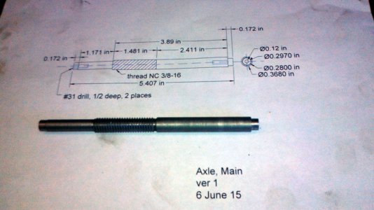
Okay, with the lathe geartrain now correct, and the tailstock aligned, I retraced yesterday's workflow and made the central section of the axle, at 1:8 scale to the original.
I compromised on a few details, using a UNC 3/8-16 thread instead of a metric Acme one, and massaged the diameters a bit to mate up with the thread's major and minor diameters. I still need to mill a long keyway on it.
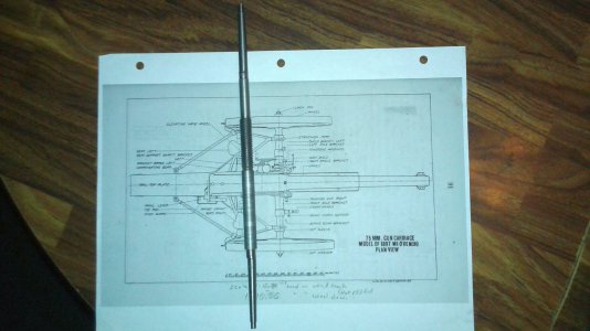
I picked the axle as a good starting place, since it's the connection point of several other assemblies. The wheels, shield, wheel brakes, mount for the recoil brake, traversal mechanism, and trail all connect to the axle. [The "trail" is the long spar that extends to the rear. The back end has a "spade" that digs into the ground to anchor the gun, and when lifted up, has the towing ring.]
Next up will be the cambered tapered ends for the axle, onto which the wheel hubs mount.
Gregaxle, main.jpg
 
And finally, the first part is done. Actually, the axle, as with the real gun, is a three-piece assembly. I had previously shown the center piece, with its threads. Onto each end go the tapered, cambered hub spindles.Axle - first part done.jpg
 
How have you registered the two tapered ends to each other? You've shown a remarkable ability and determination. Keep us informed.
 
Tom, thanks for the encouraging words.
You're just seeing the good stuff, it's been frustrating making these first few pieces. And now, I think I made the tapers about 1/4" too long and will have to redo them. But first I will do the CADrawings for the hub pieces the tapers must mate with. These two wheel hubs are each two-piece assemblies, each of which have both internal and external tapers. Cutting the external ones are straightforward enough, but the internal taper are too small (0.200) for my smallest boring bar. I'm thinking I'll try to make a D-bit style tapered reamer specifically for these hubs. I'll make these pieces from a perfectly sized piece of 1.375" aluminum rod in my scrap bin.

Not sure I totally understand your question, but the tapers aren't "registered to each other", rather, to the central piece, which is essentially cylindrical and axially drilled at each end for a 1/8" split pin. On the tapered end pieces, it's not the taper that make it tough; it's the 14 degrees of downward camber angle.
Here's how I did it, using two different axes.
First, the offset, or camber axis: the inboard end had some extra 1/2" of sacrificial material, this allowed me to hold the taper in the chuck. I drilled an center hole, offset from the true center by 0.040, at the inboard end of the spindle, into the sacrificial material that would be trimmed later. The outboard end had a on-center center hole. I turned the taper between this offset pair of centers (with the tailstock offset to give my required taper).
Then, in the 4-jaw chuck (centered this time, not offset), I removed the offset hole and drilled a new hole (with the tailstock back in alignment with the spindle) for the split pin, on-axis, going through the sacrificial section and into the taper (but off-axis to the cambered taper section). Finally, I cut off the sacrificial section and milled a camber-matching 14 degree bevel onto the inboard end. Finally, connect the spindle with the axle with the split pin.
And repeat all this for the other end.
I hope this verbal description of my workflow answers your question.
Greg
 
8 July 2015 - Making tapered D-bit reamers for the cannon's wheel hubs
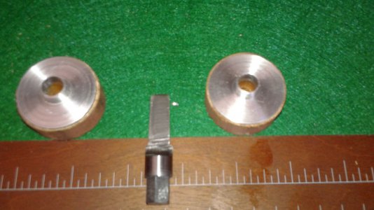
Each of the two pieces of the wheel hubs have an external taper and an internal taper and a flange with 7 holes. The internal taper of the outer hub flange seats on the external taper of the inner hub flange. The 7 wooden spokes will be clamped between these flanges by 4-40 bolts.
These tapers are 2°, so I set the compound to 1° and cut the external taper for the outer hub flange then made the tapered reamer from 1/2" drill rod using the same setting. I then milled the D-shape into the tool, and milled a hex head on the other end. Used a propane torch to harden it and tempered in the oven at 435 for an hour. It sharpened up nicely and did a nice job of reaming the aluminum flange pieces. (I used aluminum since I was worried how well my home-made reamer would work on steel. Now that I am done with its intended purpose, I'll try a test cut on steel.
On to the second taper, this time with 3/8" drill rod. It's tempering in the oven now.
Tomorrow, with the lathe's compound still at 1°, I'll turn the inner flange pieces, then into the rotary table (gluing them to wooden spools) for the seven 0.116 holes and the reaming.
Below pictures:
1. The two outer hub flanges and their tapered reamer.
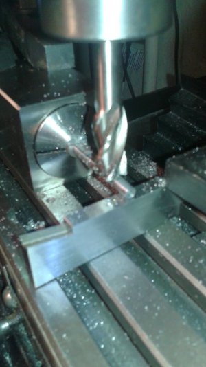
2. Having turned the taper in the lathe, here I'm milling away half of the taper to make the D-bit. That's an adjustable parallel supporting the bit's tip.
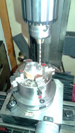
3. The outer hub flanges were glued to wooden dowels to hold them in the rotary table for drilling the bolt holes.
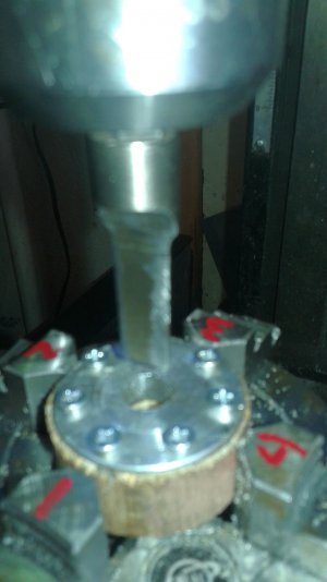
4. Then the outer hub flanges were flipped over and screwed back onto the spools for having the central hole reamed.
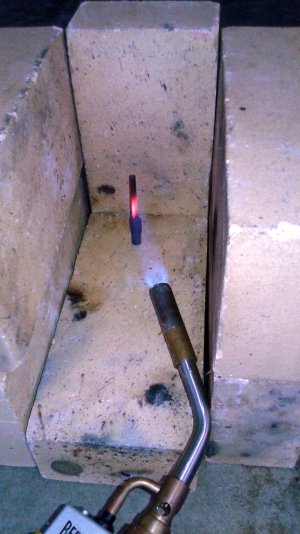
5. Having been turned and milled, the second D-bit is being hardened. (It's O1 Drill Rod.)
outer flanges with dbit reamer 2.jpg milling the dbit tapered reamer flat.jpg outer flange drilling spoke holes1.jpg outer flange being reamed.jpg reamer heat treatment.jpg
 
Back
Top