- Joined
- Nov 30, 2013
- Messages
- 13
Problem: The GPS mount I purchased for our tandem recumbent bike ended up in a bad location. During one our recent rides, the stoker, my wife, managed to kick it when she was dismounting the bike. That broke off the top of the plastic ball mount and sent the GPS scurrying across the concrete.
Solution: Make a new ball stud to replace the plastic arm on the purchased mount. But that would leave the GPS in the same position subject to another kick. So, make a new ball stud and a mount to put the GPS opposite the current mirror on the back of the captain’s seat. This also puts the GPS up where she can see it better which makes for a happier stoker and happier wife. That makes for a happier captain, too!
Challenges: How to make a ball end without the use of a ball turning tool. I’m too cheap to buy one and I haven’t ever taken the time to make one. This the perfect opportunity to “have” to make a tool, but I am on a tight schedule if we are going to ride again next weekend. So, I found an article by Guy Lautard in The Home Shop Machinist Projects One, that describes how to step turn a ball end. It was also published in the magazine Home Shop Machinist, 1983, September & October and November & December issues. Second challenge, how to design a wedge type plug similar to the bar end mirror mounts that are commonly available. It’s not too tricky, but there are a couple of considerations that are not immediately obvious.
The Design: Use what you have in the scrap bin because it’s 25 miles to the hardware store. Here's what I came up with. Earthmate GPS Mounting Bracket .pdf
Ball Stud: I stole the dimensions from the pieces of the plastic mount. That allowed me to use the socket end and the rest of the GPS cradle. I used a 10-32 x ¾” SHCS because that was what I had available.
Wedge Type Plug: Again, I used a 10-24 x 2 ½” SHCS because that is what I had available. The length of the SHCS determines the maximum length of the plug pieces. The lengths I chose were somewhat arbitrary, but had to add up 2 ½” less the thickness of the plate. The diameter of the plug upper and lower wedges is also somewhat arbitrary. It has to be small enough to slide inside the seat tube. The diameter of the hole in the wedges has to be large enough to clear the SHCS when the wedges offset in the tube. So, I drew things up in my CAD package. Then, I moved the wedges around by sliding the top one left until it hit the tube wall and the lower one along the surface of the upper one until it hit the opposite tube wall. Then I measured from the right side of the upper wedge to the right side of the SHCS to determine the maximum wall thickness of the wedges. I used that number to determine the minimum diameter of the hole through the wedges. Then I found the next convenient drill size and used that. It sounds more complicated than it really was. After some thought, I also determined that the wedges need to be able to move independent of the plug cap and the plug end. That will cause the plug cap to automatically center in the seat tube.
Machining notes:
Ball Stud: Turn and drill and tap the small end of the stud first. Then you can hold the piece in the chuck by the small end while you turn the ball. The ball on mine did not come out perfectly round, but it works OK in the socket, so I am starting over. It’s not a problem with the procedure. I just fouled up.
Wedge Type Plug: I started with ¾” aluminum round about 10” long and turned a 2” length down to 0.625” diameter. Then I drilled and tapped the end 10-24 to about ½” deep. Then I parted off the plug end. Next, I drilled the 0.305” hole down the center of the remaining 0.625” diameter piece. I then removed the round from the lathe and clamped in a bench vise. I measured 0.563 (this is not a critical dimension) from the end of the 0.625” dia, scribed at a 45 deg angle and cut with a hand hacksaw. Next, I returned the round to the lathe and parted off the lower wedge. Finished off by filing the mating surfaces of the wedges smooth.
Pictures:
1 – The completed assembly attached to the GPS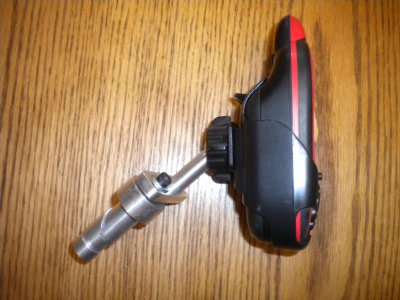
2 – Shows the assembly separate from the GPS. The assembly including the plastic socket piece will stay on the bike. The GPS slide onto the plastic piece.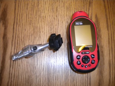
3 – Shows all the parts laid out in rough alignment. Note the washer not shown in the design drawing.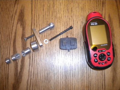
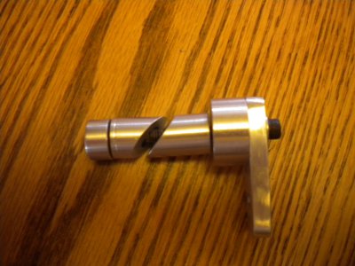
4 – Shows the plug assembly ready to slide into the seat tube.
5 – Close-up of the GPS mounted on the bike.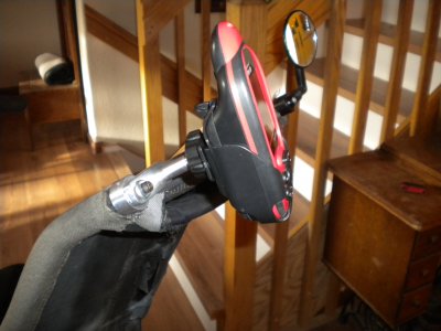
6 – A shot putting the whole thing in perspective on the bike. Yes, it is parked in the living room. It’s funny how much latitude you get when making something your wife will use.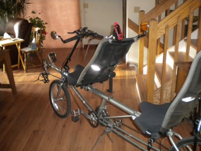
Solution: Make a new ball stud to replace the plastic arm on the purchased mount. But that would leave the GPS in the same position subject to another kick. So, make a new ball stud and a mount to put the GPS opposite the current mirror on the back of the captain’s seat. This also puts the GPS up where she can see it better which makes for a happier stoker and happier wife. That makes for a happier captain, too!
Challenges: How to make a ball end without the use of a ball turning tool. I’m too cheap to buy one and I haven’t ever taken the time to make one. This the perfect opportunity to “have” to make a tool, but I am on a tight schedule if we are going to ride again next weekend. So, I found an article by Guy Lautard in The Home Shop Machinist Projects One, that describes how to step turn a ball end. It was also published in the magazine Home Shop Machinist, 1983, September & October and November & December issues. Second challenge, how to design a wedge type plug similar to the bar end mirror mounts that are commonly available. It’s not too tricky, but there are a couple of considerations that are not immediately obvious.
The Design: Use what you have in the scrap bin because it’s 25 miles to the hardware store. Here's what I came up with. Earthmate GPS Mounting Bracket .pdf
Ball Stud: I stole the dimensions from the pieces of the plastic mount. That allowed me to use the socket end and the rest of the GPS cradle. I used a 10-32 x ¾” SHCS because that was what I had available.
Wedge Type Plug: Again, I used a 10-24 x 2 ½” SHCS because that is what I had available. The length of the SHCS determines the maximum length of the plug pieces. The lengths I chose were somewhat arbitrary, but had to add up 2 ½” less the thickness of the plate. The diameter of the plug upper and lower wedges is also somewhat arbitrary. It has to be small enough to slide inside the seat tube. The diameter of the hole in the wedges has to be large enough to clear the SHCS when the wedges offset in the tube. So, I drew things up in my CAD package. Then, I moved the wedges around by sliding the top one left until it hit the tube wall and the lower one along the surface of the upper one until it hit the opposite tube wall. Then I measured from the right side of the upper wedge to the right side of the SHCS to determine the maximum wall thickness of the wedges. I used that number to determine the minimum diameter of the hole through the wedges. Then I found the next convenient drill size and used that. It sounds more complicated than it really was. After some thought, I also determined that the wedges need to be able to move independent of the plug cap and the plug end. That will cause the plug cap to automatically center in the seat tube.
Machining notes:
Ball Stud: Turn and drill and tap the small end of the stud first. Then you can hold the piece in the chuck by the small end while you turn the ball. The ball on mine did not come out perfectly round, but it works OK in the socket, so I am starting over. It’s not a problem with the procedure. I just fouled up.
Wedge Type Plug: I started with ¾” aluminum round about 10” long and turned a 2” length down to 0.625” diameter. Then I drilled and tapped the end 10-24 to about ½” deep. Then I parted off the plug end. Next, I drilled the 0.305” hole down the center of the remaining 0.625” diameter piece. I then removed the round from the lathe and clamped in a bench vise. I measured 0.563 (this is not a critical dimension) from the end of the 0.625” dia, scribed at a 45 deg angle and cut with a hand hacksaw. Next, I returned the round to the lathe and parted off the lower wedge. Finished off by filing the mating surfaces of the wedges smooth.
Pictures:
1 – The completed assembly attached to the GPS

2 – Shows the assembly separate from the GPS. The assembly including the plastic socket piece will stay on the bike. The GPS slide onto the plastic piece.

3 – Shows all the parts laid out in rough alignment. Note the washer not shown in the design drawing.

4 – Shows the plug assembly ready to slide into the seat tube.

5 – Close-up of the GPS mounted on the bike.

6 – A shot putting the whole thing in perspective on the bike. Yes, it is parked in the living room. It’s funny how much latitude you get when making something your wife will use.


