-
Welcome back Guest! Did you know you can mentor other members here at H-M? If not, please check out our Relaunch of Hobby Machinist Mentoring Program!
You are using an out of date browser. It may not display this or other websites correctly.
You should upgrade or use an alternative browser.
You should upgrade or use an alternative browser.
Got My First Machine!
- Thread starter Izzy
- Start date
@Ulma Doctor, @talvare where did everyone go? Lol
- Joined
- Feb 2, 2013
- Messages
- 3,622
sorry i have a crazy job schedule- i saw the pictures
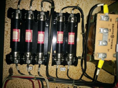
i can't really read your fuse amp sizes, but they are most likely relatively low
the contactor coils will need to be appropriate for your control voltage
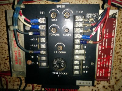
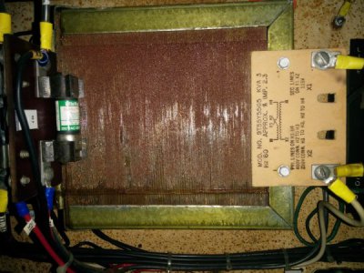
i see that the input for the dc control unit is 115v and the transformer is 115v output
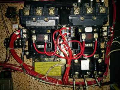
i could not clearly see the contactors, a slight close up of them side by side may help out
sorry for the delay in reply
- Joined
- Feb 2, 2013
- Messages
- 3,622
are we talking about the spindle motor or another motor?Forgot to mention it looks like it's a 4 wire motor atleast thats all I saw when I opened up the junction box...
Hey no worries no rush just didn't wana get left behind lol. I'll be at the machine again this weekend and I'll be able to take more pics, the contactor is the thing with the white reset button right?
Yes I was talking about the spindle motor the male plug/wires lead Into the junction box and just connect to 3 wires and one to ground
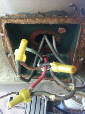
Yes I was talking about the spindle motor the male plug/wires lead Into the junction box and just connect to 3 wires and one to ground

- Joined
- Apr 4, 2016
- Messages
- 843
Sorry for the late response. Just haven't had time to get on the forum lately. Anyway, you will need to re-do the connections in the motor junction box. The wiring diagram is on the lower right corner of the motor name plate. You will wire nut number's 4, 5, and 6 together. Then wire nut #1, #7 and L1 together, then #8, #2 and L2 together, then #9, #3 and L3 together (L1, L2, and L3 are your three phase power supply to the motor). I'm having a very hard time trying to read details on the wiring diagrams and various electrical components in the control panel. I'm going to see if I can enlarge the photos and I'll get back to you.
Ted
Ted
- Joined
- Apr 4, 2016
- Messages
- 843
Izzy,
I think you're going to have to make another attempt at getting some higher resolution photos of those wiring diagrams. They look like good diagrams but I just can't read the lettering and numbers. You may need to take close-up shots in sections and then we'll try to arrange them properly to compose the complete wiring diagram. You mentioned that you had a chart for the heaters. That should give you the info you need to purchase new heaters for 230V operation. In case you don't know, the heaters are the little blocks with two screws in them that the T1, T2 and T3 wires are connected to on the bottom of the reversing starter in your photo. I think those are Allen-Bradley magnetic starters. You'll need to read the data plates and verify that. The heaters have to be the same brand as the starters because different manufacturers components won't interchange. I'll keep trying to come up with more info for you and report back.
Ted


