g-code generating ideas

Dr.Fiero

Active User
Registered
Joined
Feb 16, 2013
Messages
160
I'm trying to find the easiest (of course!) way to make a square toothed gear.

There was a post earlier with a killer link to a site that made EXACTLY what I wanted:
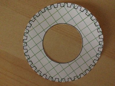
photo.JPG

As you can see, I could design it, print it, cut it out and try it even!
(it's a timing wheel for my twist on the $25 tach BTW!)

I suck at autoCAD though, which is the only other way I could think of doing it - no way I'm going to free hand that and hope to get it right!
I can run a DXF or whatever through CamBAM etc and generate the g-code.

There's 36 teeth, 100mm OD, and a 55mm center hole.

Any other ideas? I'm going to need to do at least one more, since I'm taching my drill press too (why not eh?!).

photo.JPG
 
I'm trying to find the easiest (of course!) way to make a square toothed gear.

There was a post earlier with a killer link to a site that made EXACTLY what I wanted:
View attachment 48997

As you can see, I could design it, print it, cut it out and try it even!
(it's a timing wheel for my twist on the $25 tach BTW!)

I suck at autoCAD though, which is the only other way I could think of doing it - no way I'm going to free hand that and hope to get it right!
I can run a DXF or whatever through CamBAM etc and generate the g-code.

There's 36 teeth, 100mm OD, and a 55mm center hole.

Any other ideas? I'm going to need to do at least one more, since I'm taching my drill press too (why not eh?!).


http://www.youtube.com/watch?v=7zMgJXMHcNs
 
Shouldn't one toothe be omitted to indicate the zero location for a full revolution" I am totally unfamiliar but I used to do auto stuff and they always had one wide gap or one wide solid space to set the sychronization between the cam and the crank in the computer. Just wondering, not trying to make it any more diffisult/

Bob

Totally know what you mean - missing tooth is required for crank & cam position sensors so the ECM knows if you're at the top of the compression or firing stroke.
(done auto electronics for years!)

This is purely a rotational speed thing though, where you don't need an index pulse. The wheel just slices up the time and creates a pulse stream.
I could do this with 4 tabs, or 100. I just picked 36 since it divides nicely - and fits well on a 4" wheel!

Now, if I was doing threading, and wanted to feed back into Mach3 - I'd need that index! Easy though, just cut off a tab.
 
Forgot to mention (you know - you see something in your own head and assume it's obvious?!)

This is made out of ~16ga sheet metal!

As soon as I can come up with a DXF (etc), it's thin enough that I can make it on my existing small CNC machine.
Then I can finish up the lathe.
Which I can then use to make the last few parts for my CNC mill.
Which I can then use to make parts for the existing small CNC machine that will no doubt get broken in the process.....

.... and so the continuing cycle of parts begins. :D
 
i'd just drill holes in 10 degree locations for it to work, your using a infared sensor right
and type in the manual mode A10, drill the hole a20, drill the hole, A30, A40 ect
then go to 0.0 and do the g-code for the outside cut then the inside bore
steve


edit: i was thinking you had a 4 axis mill already
do you have a rotary table same thing and probably faster
 
I took a quick shot at it in Alibre. Gear.DXF in Gear.ZIP. The teeth are evenly spaced teeth and valleys, cut 0.223" deep with 1/16" fillets.
Try it, and if you want other dimensions I'll take another shot at it.

I need the practice. ;)

Ken
 

Attachments

  • Gear.zip
    11.1 KB · Views: 11
off topic
but mach3 uses only a single pulse now and wont work with more than one per revolution on the newer versions
steve
 
I took a quick shot at it in Alibre. Gear.DXF in Gear.ZIP. The teeth are evenly spaced teeth and valleys, cut 0.223" deep with 1/16" fillets.
Try it, and if you want other dimensions I'll take another shot at it.

I need the practice. ;)

Ken

Awesome! A quick mod to the center hub up to 55mm and it looks about right (I suck at it - but do actually own Alibre also!).
I'm sure it took me longer to resize the hub than it took you to do most of the drawing. :whistle:

I'll go and try to cut it out after dinner, and I'll report back.
 
For those without a CNC mill, a chain sprocket with the right number of teeth is a quick-and-dirty chopper.
 
Back
Top