Fabricating some spring-loaded travel stops

jmarkwolf

Active User
H-M Supporter Gold Member
Joined
Nov 9, 2012
Messages
556
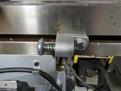
I need to fabricate some custom spring-loaded travel stop similar to the pic below. Commonly available ones don't have the proper dimensions for my application.

But am not finding something suitable to serve as the "plunger". I thought maybe some un-threaded weld studs with a round head might fill the bill, but how to hold such a thing while cutting a groove for a circlip, or an axial hole in the end for a small screw and washer?

Any ideas?
 

Attachments

  • X axis stops.jpg
    X axis stops.jpg
    117.4 KB · Views: 19
  • Bolt_Expo_weld_studs.jpg
    Bolt_Expo_weld_studs.jpg
    13.7 KB · Views: 20
make a ring that fits the shaft, split it, then clamp it in your lathe chuck. Might be a lot of effort for what you want to do, but that's how I'd do it.

GsT
 
Drill a cross hole and add a washer and pin, A simple drill press operation.

Personally though, if I wanted a circlip, I would just turn the neck on the part, cut my groove for the circlip and part it off. By the time it took to write an order, I'd be done.
 
OP here:

Found a good solution for the "plunger". Found these "wire lock round pins" (clevis pin?) at the local Tractor Supply.

I think they'll work great.

I like RJ's idea about the cross hole too.
 

Attachments

  • Wire lock round pin.jpg
    Wire lock round pin.jpg
    138.3 KB · Views: 4
OP here with an update:

Below is a pic of the trial fitting of one of the new travel stops I've fabricated, for my new Servo200 knee lift installation. I still need to locate and drill for the weld stud (from another local hardware store) that will affix the stop to the track.

The "plunger" is a clevis pin from the local Tractor Supply, the spring is from the local Ace Hardware, and the aluminum is from my junk box.

I had to re-align the track a little bit from the original "standoff" from the column but it required only a change in length to the spacers between the track and the column of my Acer e-Mill which has quite a taper. In order to accommodate this taper, and to the keep the track straight, I had to fix some spacers between the track and the surface of the column (visible at the top of the track and underneath the stop, while the bottom end of the track is fastened directly to the side of the column.
 

Attachments

  • New_Servo200_knee_travel_stop.jpg
    New_Servo200_knee_travel_stop.jpg
    122 KB · Views: 15
Last edited:
Update from OP here:

I've completed and implemented the travel stops. Pics below.

The column on my Acer e-Mill is quite tapered. The bottom end of the approx 16in long Servo supplied track is screwed directly to the column. The top end of the track is mounted to the column with a 1in spacer, as well as an interim spacer (see pic). This keeps the track located such that the switches fall on the center of the travel stops.

It was labor intensive to fabricate these parts, but gratifying to see the end result.
 

Attachments

  • New fabricated travel stops.jpg
    New fabricated travel stops.jpg
    139.7 KB · Views: 10
  • Latest_Servo200_limit_track.jpg
    Latest_Servo200_limit_track.jpg
    163.7 KB · Views: 10
Back
Top