- Joined
- Feb 2, 2014
- Messages
- 1,068
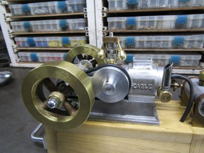
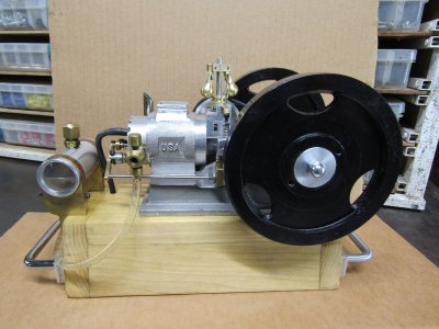
Two years ago I built a Bob Shores Eagle engine this is it when it was competed in 2020.
It has been very reliable and gets ran ever month or so as do all my models.
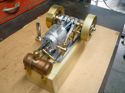
I have made some minor changes over the time like a see through gas tank and battery upgrades but basically it is just the way it was then.
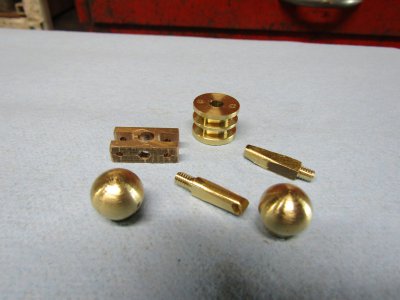
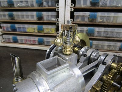
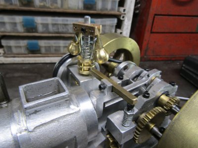
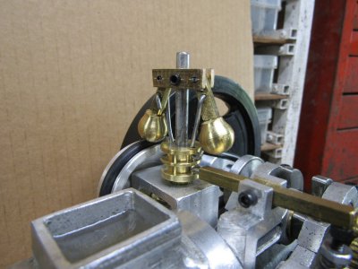
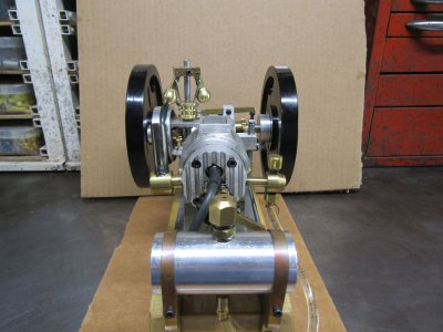
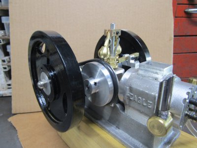
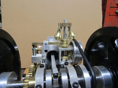
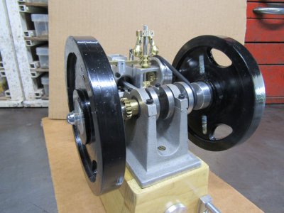
I made a flying ball governor for my engine called "Red" last month and with that built and new governor I was able to get the slow speed down to 480rpms. Now the Eagle is a solid engine but because of the way it is built it is not a slow runner. At last check it likes to run at 1200 to 1400rpms so why not make a new governor for it and see if I can slow it down.
The Eagle is a much smaller engine so the governor will have to be smaller, a lot smaller actually about 1/4 the size.
I started with a block of aluminum, some 3/16" shaft and some 0.560 brass stock.
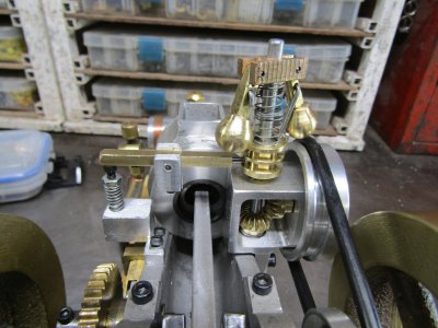
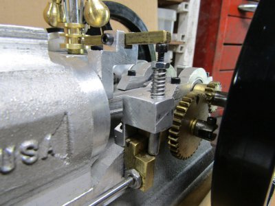
The miter gears are 0.560 in diameter with 18 teeth and cut with Mod 0.7 gear cutter.
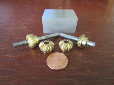
I made a couple of extra gears just in case they are needed later.
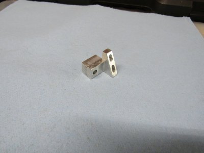
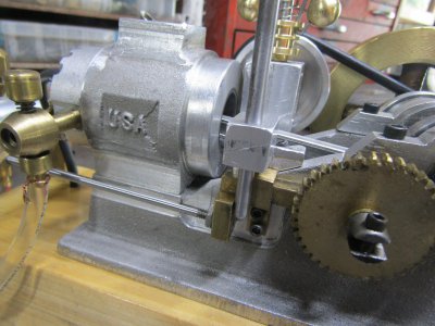
There isn't much room on the Eagle so the gear case was a job in itself with lots of cutting and fitting and thinking.
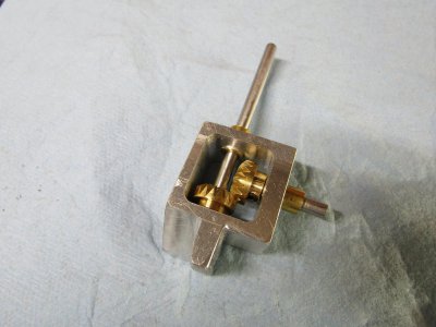
I had forgotten how much I hated these little parts as my fingers don't work as well as they used to.
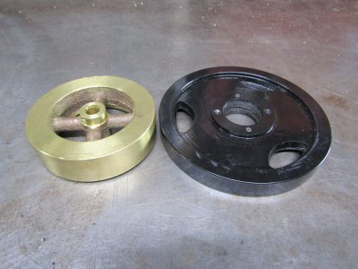
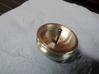
In order for the driven pulley to line up with the crankshaft it has to fit over the gear box housing.
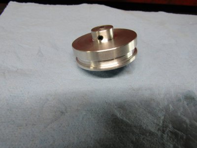
This shows how the pulley was hollowed out on the inside to fit over the gear box.
More later
Thanks for looking
Ray
It has been very reliable and gets ran ever month or so as do all my models.

I have made some minor changes over the time like a see through gas tank and battery upgrades but basically it is just the way it was then.
I made a flying ball governor for my engine called "Red" last month and with that built and new governor I was able to get the slow speed down to 480rpms. Now the Eagle is a solid engine but because of the way it is built it is not a slow runner. At last check it likes to run at 1200 to 1400rpms so why not make a new governor for it and see if I can slow it down.
The Eagle is a much smaller engine so the governor will have to be smaller, a lot smaller actually about 1/4 the size.
I started with a block of aluminum, some 3/16" shaft and some 0.560 brass stock.
The miter gears are 0.560 in diameter with 18 teeth and cut with Mod 0.7 gear cutter.

I made a couple of extra gears just in case they are needed later.
There isn't much room on the Eagle so the gear case was a job in itself with lots of cutting and fitting and thinking.

I had forgotten how much I hated these little parts as my fingers don't work as well as they used to.
In order for the driven pulley to line up with the crankshaft it has to fit over the gear box housing.

This shows how the pulley was hollowed out on the inside to fit over the gear box.

More later
Thanks for looking
Ray


