-
Welcome back Guest! Did you know you can mentor other members here at H-M? If not, please check out our Relaunch of Hobby Machinist Mentoring Program!
You are using an out of date browser. It may not display this or other websites correctly.
You should upgrade or use an alternative browser.
You should upgrade or use an alternative browser.
After exhausting research and re-reading your answer to the thread several times I figured it out. Works out great. I do have to say that the original motor only had 4 wires and no jumper on the switch. God only knows how that worked. I couldn't have figured that out without your response to that thread. Thanks.
- Joined
- Jul 6, 2016
- Messages
- 102
I really need some help regarding this topic
I have told Logan machines what is a 1821 but the lathe that I choose to use everyday is a 1946 820. It's flawless and I just love it.
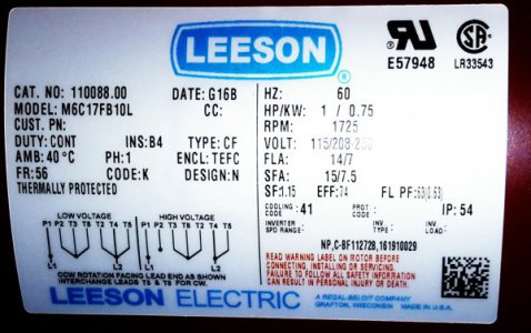
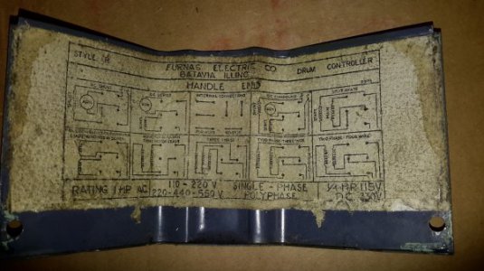
I am totally and utterly lost when it comes to hiring this motor no looking at the schematic I could wire it to a plug plug it in and have is properly to the drum switch if I look up a fifties images they are the same connection layout that my trim switch has. I will add some images at the bottom that'll help. For now I just want to hook it up to standard 115-volt service because I have to go buy everything to run a new 220 into my shop area I do not want to put it on the same 220 line is my Mill is on because they often are running at the same time. At any rate I don't know why I'm having such a hard time fathoming what I need to do I just purchased a brand Leeson 1 horsepower motor for the Logan. The only thing I know is what controls forward and reverse is T5 T8.
I'm going to post some images please help me someone I'm just this is like a Rubik's Cube to me I can't rationalize how to arrange these connections for some reason
, I uploaded a PDF that shows my Motors wiring guide my God this is so embarrassing for me but I really need help
Attachments
- Joined
- May 2, 2011
- Messages
- 812
I can do this but I need a schematic of the reversing switch as well. On the wiring diagram, low voltage puts the two run windings in series, high voltage puts then in parallel. As you rightly say, you change direction by swapping the polarity of the start winding, so you need to arrange the forward/reverse switch to swap T5 and T8 over. I assume the reversing switch has a centre off position. Incidentally, it is immaterial , but I do not recognise the symbol to the left of the thermal trip at the top of the drawing, just under the letter L in "Line" Anyone enlighten me?
Phil
Phil
Because your switch my not require jumper.
After exhausting research and re-reading your answer to the thread several times I figured it out. Works out great. I do have to say that the original motor only had 4 wires and no jumper on the switch. God only knows how that worked. I couldn't have figured that out without your response to that thread. Thanks.
- Joined
- Feb 2, 2013
- Messages
- 3,625
Hi Phil,I can do this but I need a schematic of the reversing switch as well. On the wiring diagram, low voltage puts the two run windings in series, high voltage puts then in parallel. As you rightly say, you change direction by swapping the polarity of the start winding, so you need to arrange the forward/reverse switch to swap T5 and T8 over. I assume the reversing switch has a centre off position. Incidentally, it is immaterial , but I do not recognise the symbol to the left of the thermal trip at the top of the drawing, just under the letter L in "Line" Anyone enlighten me?
Phil
it appears to be a drawn in picture of a crimp connector

or, possibly the reset switch for the thermal protection device.
- Joined
- Jul 6, 2016
- Messages
- 102
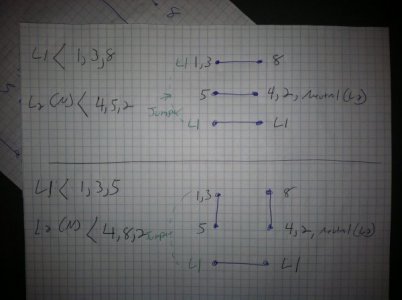
Is this close? I found this in another thread and it looks close I'm not sure about the jumper though everytime I think I'm understanding what's going on I get confused it's really ridiculous I should have this down it's only a few wires for Christ's sake my wiring doesn't seem to show t1 I have P1 and P2
This is where some of my confusion is
And thank you for taking the time to help me I appreciate it completely


This is where some of my confusion is
And thank you for taking the time to help me I appreciate it completely


Last edited:


