DRO on HF 44142

Happycamper

Active User
Registered
Joined
Mar 20, 2013
Messages
153
Got my Accuremote DRO scales in from DavidH. Measured them, cut and ground the ends square. Now to start marking, drilling and tapping holes to mount. I see I'm going to need some extensions for the mini USB cables in order to mount them where I want. I noticed that there are a lot of small threaded holes on the back and sides of the reading heads. It looks like some are for gib adjustments but don't know. I emailed DavidH and he will check w the factory/distributor Monday and let me know about the holes. At worst I'll leave as is but could install small screws to fill the holes. I'll post pics later when I have some time.
 
Are you questioning the reason for the extra holes and whether to leave them alone? I have a set on my Grizzly mill and aside from the two screws to mount a bracket to the reader, I did nothing extra.
 
Are you questioning the reason for the extra holes and whether to leave them alone? I have a set on my Grizzly mill and aside from the two screws to mount a bracket to the reader, I did nothing extra.

do you have any pix's of your installation ? I would be interested in putting them on my facebook page with the others if you share .
 
David, still working on it. We have company this weekend and won't be able to do anything until Tuesday. Need to get some aluminum angle that I'm going to use as a cover and an assortment of screws and nuts to use as well as the USB extension cables. I'll take pics as I go and post them.
 
As far as all the screw holes, I'll know more after Monday. I may still get a bunch of set screws and fill them in just to make the unit less susceptible to fluids. But it sure looks like that the holes on the edges were/are for gib adjustment but don't know. Looking at Yuri's comparison of the Accuremote to the Igaging scale on his site He notes a screw for gib adjustment.
 
do you have any pix's of your installation ? I would be interested in putting them on my facebook page with the others if you share .

Everything decent is in this flickr set: http://www.flickr.com/photos/smudgemo/sets/72157632840629438/ I'm not suggesting my work is of superior aesthetic quality, but it works very well. If you'd like any other angles, be sure to tell me soon because the mill is on Craigslist.

Feel free to use them as you need, but if it's profitable and you want to thank me, you can hook me up with a deal on a spindle-style unit for my new mill. I am going to want one sooner or later...
 
mr smudgo, I will check out your pix tonite, thanks for the offer. I would be more than happy to turn this project over to anyone that wants.
there is no money to be made.

as far as the little holes on the edge of the display units, the official answer was, " no reason for them could be seen, possibly the mfg has something else in mind for them." I'd just leave them.

whatever you can offer for other guys to see, thats what I will put up on my facebook site. its just for others to get ideas for mounting. :)

I really like my dro's, and with the power adapter for larger batterys also connected to some lights I will consider my self my own hero. . .

- - - Updated - - -

Everything decent is in this flickr set: http://www.flickr.com/photos/smudgemo/sets/72157632840629438/ I'm not suggesting my work is of superior aesthetic quality, but it works very well. If you'd like any other angles, be sure to tell me soon because the mill is on Craigslist.

Feel free to use them as you need, but if it's profitable and you want to thank me, you can hook me up with a deal on a spindle-style unit for my new mill. I am going to want one sooner or later...


flicker will not allow "copy and save" or "save" nice pictures of your machines. you saving the Bridgeport looking mill ?
 
Well it's done. Tested it out yesterday and the Accuremotes worked like a charm.
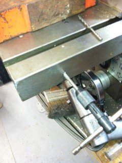
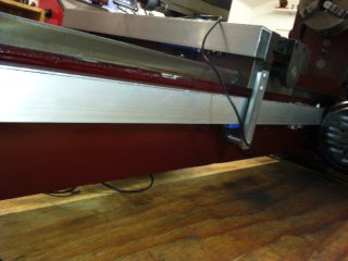
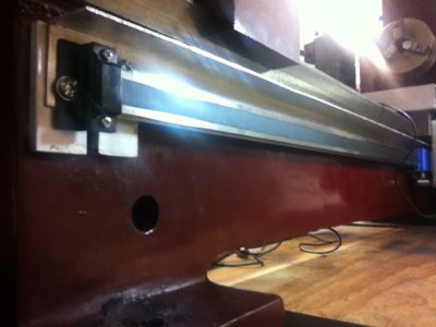
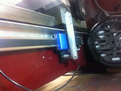
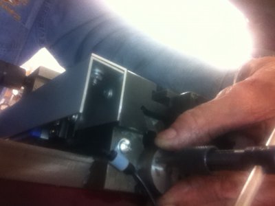
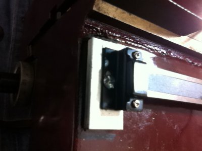
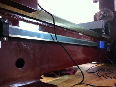
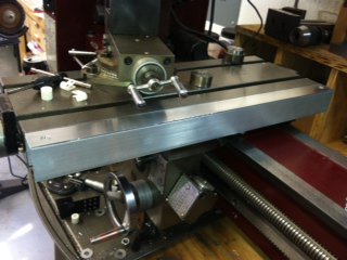
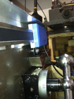
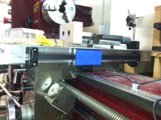
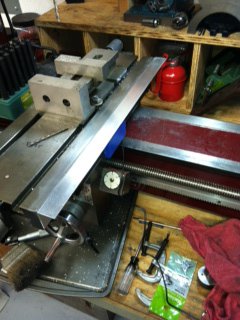
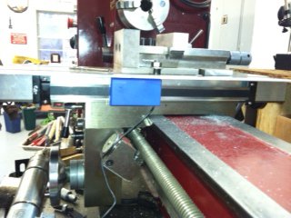
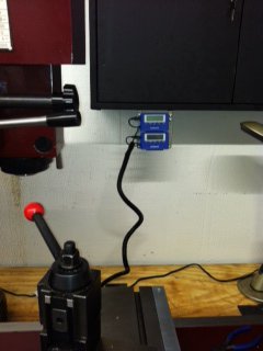
when I got them in, I was a little hesitant since there are no installation instructions at all. Looking on youtube DROPros have some videos but pertain to other lathes. You can get a general idea though of what is needed to be done. The brackets shipped with the units(make not David) were worthless in my installation. I modified two of the angle brackets making them in to flat brackets and used them on the back of the reading head. I used the two mounting brackets on each end of the bars but that was it. If you do decide to put them on a 44142 you need to think it through, take it step by step and be prepared to make brackets and the scarf covers. I used 1 1/2" angle aluminum and cut the tops down to 1". They work perfectly. The rest of the mounts/brackets I made from stuff laying around, you know how that is. In mounting the scales on the crossslide, I was faced with having to cover the oil holes on the side of the cross slide. I needed up mounting it on the right side where the locks are located. This meant making some new shorter screws that will clear the reading head and still be accessible with a screw driver. Mounting the scales parallel to the movement was fairly easy. There are no instructions or technical specs on how parallel they need to be or what the tolerances can be.(David take note) I mounted my aluminum angle cover directily to the cross slide and level with the top of it. I then mounted the scale on the cross slide with the reading head mounted to the saddle. I checked the scale with digital calipers to be sure the were parallel with the cross slide. Then the other piece of aluminum angle was secured making a good protective cover for the scale and reading head. I mounted the X scale to the back of the bed of the lathe. I checked the spacing from the back of the saddle and ended up using some 1/4" x 1" aluminum for spacers. I cleared the back of the work bench the lathe is setting on in order to work on the back of the lathe. Because of the motor location I had to mount the head end of the scale at the point where the back of the motor is in relation to the bed. I had ordered the 38" scale but could have gotten by with the 24" scale. I mounted two pieces of the 1/4"x1" flat to the bed and mounted the aluminum cover to those. Then used two more pieces of the flat for spaces for the scale. I made a bracket out of some 1/4"x 1" steel flat scrap and mouted it to the back of the saddle on the tail stock side. I measured the distance from this piece to the bracket on the reading head and made a spacer out of some 1/2" round stock and drilled it and mounted it to the reading head. I had set the scale in place by measuring from the top of the ways to the top of the scale making it parallel to the lathe bed. Then put my other piece of aluminum angle on as the back of the cover for the scale. I used strain reliefs on the wires coming from the heads and covered them with some automotive wire loom tubing. I started to use aluminum flex cable but didn't. I also mounted the wire loom using clamps. I had originally wanted to place the receivers on the top of my gear bos but that would have required using some mini USB extensions. I ended up installing a plate under my wall tool cabinets which is probably a better location. It took me three days to do it all working about 5 hrs a day. I have since used them to thread a couple of barrels and they worked perfectly. So here are some pics taken from my phone. photo 1.JPGphoto12.JPGphoto10.JPGphoto 11.JPGphoto 9.JPGphoto 8.JPGphoto 7.JPGphoto 6.JPGphoto 5.JPGphoto 4.JPGphoto 3.JPGphoto 2.JPGphoto13.JPG

photo 1.JPG photo 2.JPG photo 3.JPG photo 4.JPG photo 5.JPG photo 6.JPG photo 7.JPG photo 8.JPG photo 9.JPG photo 11.JPG photo10.JPG photo12.JPG photo13.JPG
 
Back
Top