- Joined
- Nov 23, 2014
- Messages
- 2,606
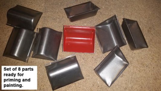
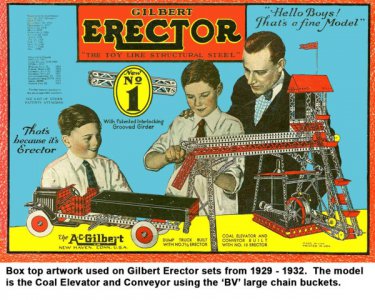
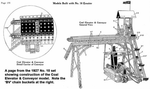
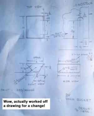
I usually document these types of projects in the POTD string but this one was a little more involved. A lot of my shop projects are reproductions of Erector set parts from the 1910’s through 1950’s. Latest part is a die set for making part number “BV” large chain buckets. These buckets were included in the largest sets from 1927 – 1932; sets of 8 were in the inventories. There were a number of conveyor type models that used them. And as with all Erector set parts from this era, they aren’t making them anymore so there is a limited supply and market for the parts.
By the way, lots of photos here so the process will take a couple of messages. Please bear with me, I'm known at work for going on and on and on . . .
The BV’s were made from 0.040” steel. Some other Erector enthusiasts have reproduced them from brass; cut, bend and soldered together. Original parts were made in one piece from a draw die and trimmed to shape. I’ve made what I call “smash dies” before; basically put a blank between two pieces of steel and mash the blank to shape. However, this part has a pretty deep draw (2” across the opening of the bucket, ¾” depth) and couldn’t be formed by mashing as the sides would wrinkle as the sheet steel flows into the lower die.
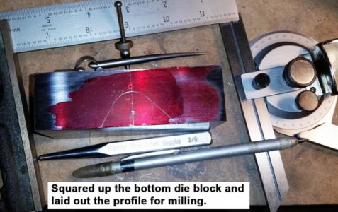
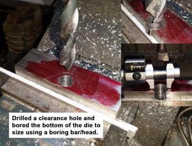
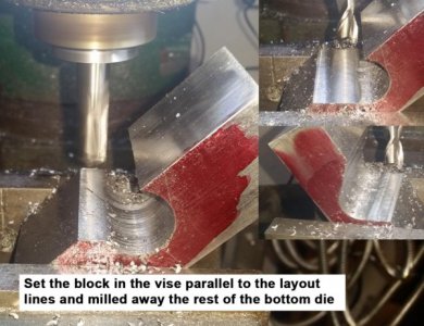
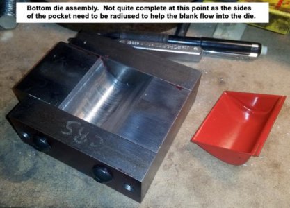
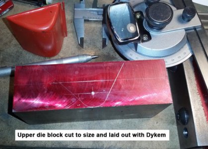
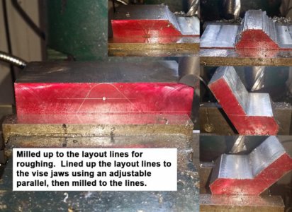
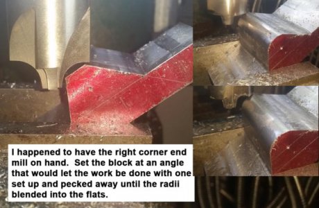
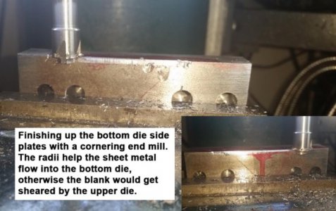
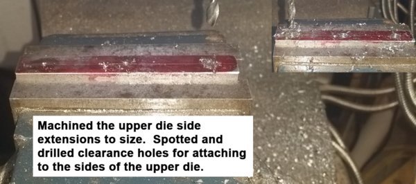
The upper and lower dies were made in three pieces from CRS. Nothing too spectacular there; Dykem up the blocks after they were squared and cut to size, then profiled on the mill.
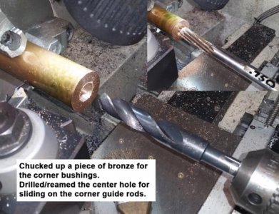
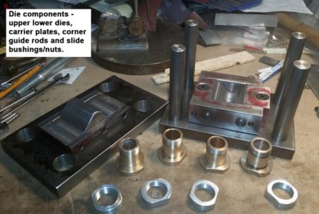
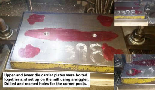
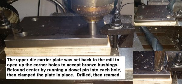
I’m not familiar with the proper terminology for the pieces/parts here, but made what I’ll call a die carrier next. The upper and lower dies need to be aligned with each other while pressing a blank. I used two ¾” thick pieces of HRS for the carrier. These were bolted together as holes for ¾” steel guide rods would make sure the two plates stayed registered to each other. The bottom plate has the ¾” rods attached to it with screws from the side to hold the rods in place. The upper plate slides up/down during forming of the part, I decided to make some 1” OD, ¾” ID bronze bushings for the upper plate as guides on the ¾” rods.
That meant opening up the ¾” holes in the upper plate to 1”. A ¾” dowel pin was put in a collet and fed into an upper plate holes. Then the plate was clamped down on the mill table. This put the mill spindle back on center.
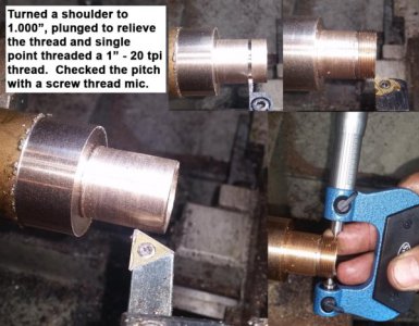
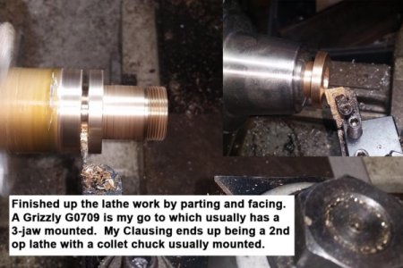
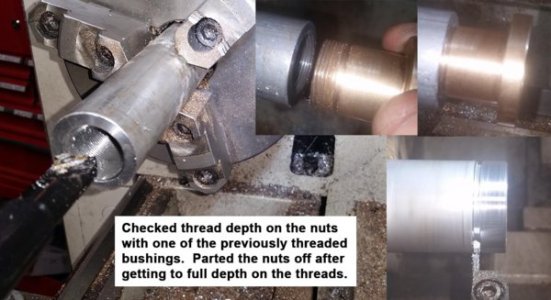
The bronze bushings were turned on the lathe. I have 1”-8 and 1”-14 taps and dies, but decided to go with a 1”-20 thread on the bushing and attaching nuts. That meant single-point threading the parts. Sure, it would have been easier to use a 1”-14 tap/die, but I like going back to the basics every once in a while to refresh myself on the process. The bushings were made first and cut to depth using a thread pitch mic. I cheated a bit and didn’t do the calculation for the pitch diameter. I figured if a ¼”-20 thread calls for a pitch diameter of 0.2175”, a 1”-20 thread should be the same delta from the major diameter of 1.000” or 0.9675”.
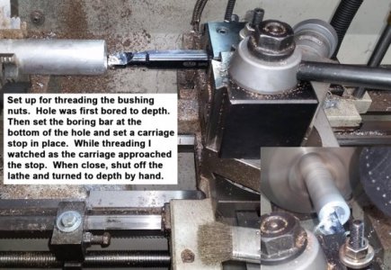
The 1”-20 nuts were turned from aluminum. First bored to size. Again, cheated a bit and didn’t consult Machinery’s Handbook. Instead, took 0.25” minus the diameter of the #7 tap drill (0.201”) and got a delta of 0.049”. Subtracted that from 1” for a bore diameter of 0.951”. Used a Shars internal threading boring bar with a 16IR insert to do the threading.
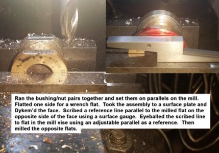
Went back to the mill to knock a flat on the bushings and nuts for getting ahold of them with a wrench. Dykem’d the surfaces after making the first cut, then scribed a reference line with a surface gauge parallel to the first cut. Lined up the scribed line on the bushings/nuts with an adjustable parallel on the mill vise jaw.
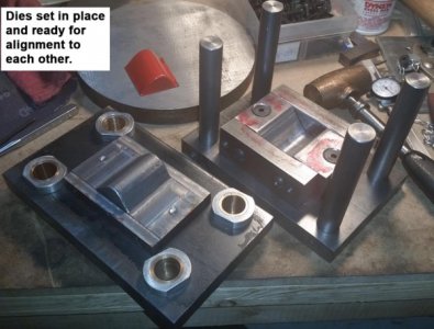
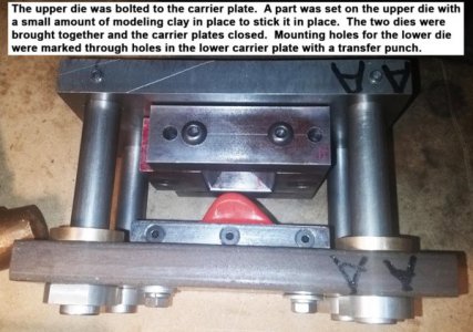
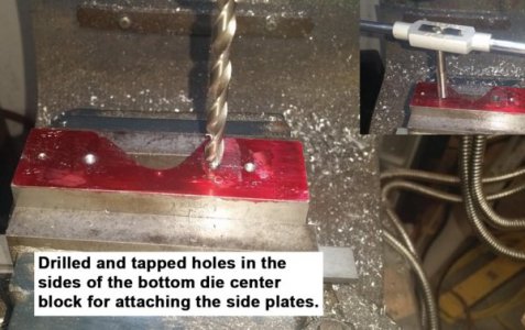
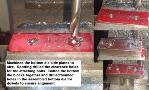
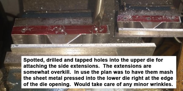
I used the holes previously drilled into the carrier plates to attach each die. First did the top die. Drilled/tapped a couple of holes and bolted the die to the upper carrier plate. Then I set the stamped part in the lower die, set the lower die in place and dropped the lower die carrier plate onto the lower die. Transfer punched holes through the lower plate onto the lower die, drilled/tapped the die for attaching to the plate.
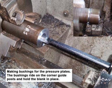
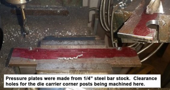
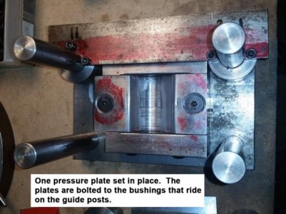
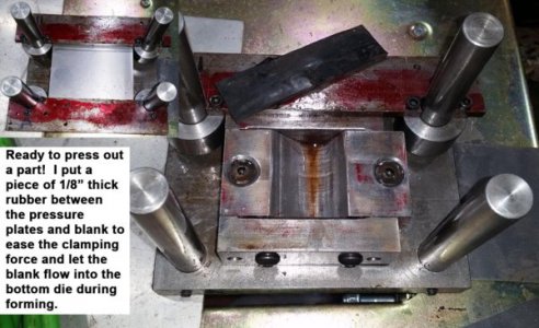
Next came the pressure plates. These are two plates of steel that more or less clamp the blank to the bottom die to hold it down during the drawing process. Set a piece of paper on the top of a coffee mug and push down into the mug with your fingers; the sides of the paper will fold up and wrinkle as you push down. Same thing for the die here. Started with a set of steel bushings that ride on the ¾” guide rods and screwed a couple of ¼” plates to the bushings.
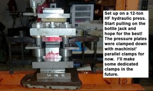
OK, ready to try it out! A tool & die buddy of mine recommended using a thin sheet of rubber (used 1/8” thick) between the pressure plate and blank. The rubber allows the blank to slip a bit as the upper die is pressed into the lower. It still holds the blank down per my coffee cup example above. For now I’m clamping the pressure plates to the bottom die plate with parallel clamps. I’ll eventually speed things up with some dedicated, pre-adjusted clamps, but was anxious to try things out!
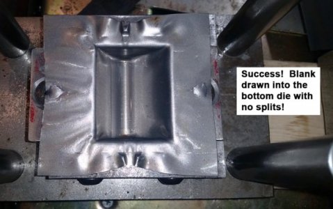
Well, mixed success . . . I split a lot of blanks. Ground some radii on the pressure plates and lower die edges, played with the rubber above and below the pressure plate too. Finally came up with a pretty good combo of rubber on the blank squeezed by the parallel clamps biased slightly towards one end.
Pressing was done on a Harbor Freight 12-ton shop press with an air over hydraulic cylinder. Sure nice to squeeze the trigger and watch the ram move instead of pumping away by hand. There are still some wrinkles in the blank, but they’re on the edges, not down into the part so things were looking up! I managed to make a dozen or so parts pretty quickly with no splits or wrinkles.
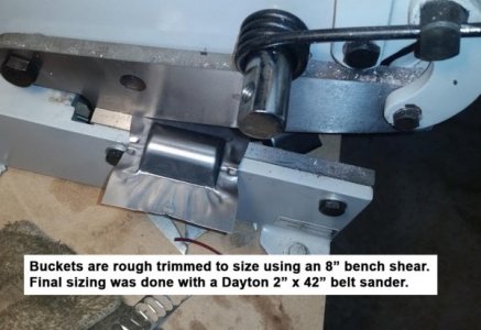
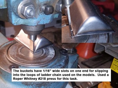
After drawing, the blank was trimmed to size. I used an 8” bench shear for that which worked great. Then to the Dayton 2” x 42” belt sander to take the part to its final shape. Lastly, a pair of 1/16” wide slots were cut into one end of the buckets using a Roper Whitney #218 punch press. That leaves a couple of more or less pins on the ends of the bucket for slipping into loops on the ladder chain used on the models.
All in all a really good learning project for me, but still lots to figure out. Sure seems like die making is more of an art than a science at this point, but I’m one for one right now! Should have plenty of these made up for an upcoming show in July.
Bruce


Last edited:


