Doall 1612-3 SN 152-66758

fillister

Registered
Registered
Joined
Feb 12, 2014
Messages
36
Hello all

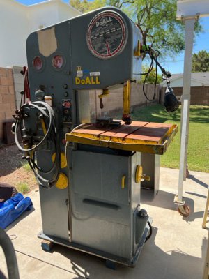
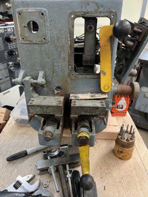
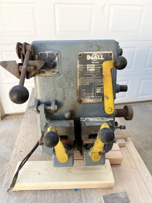
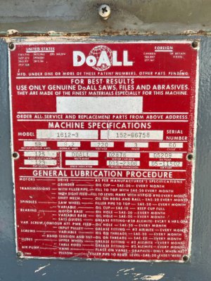
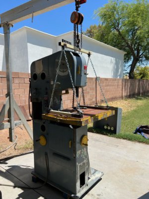
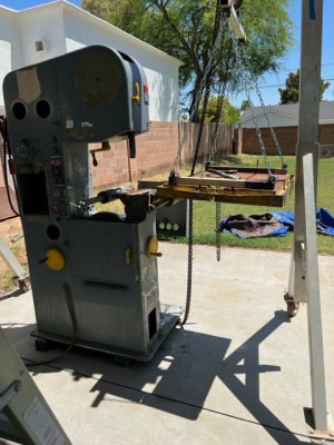
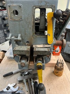
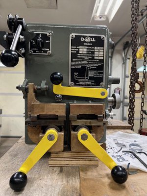
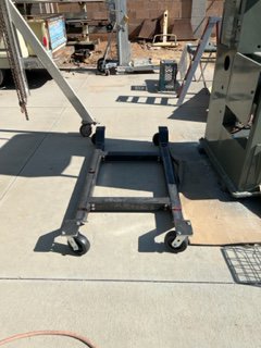
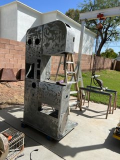
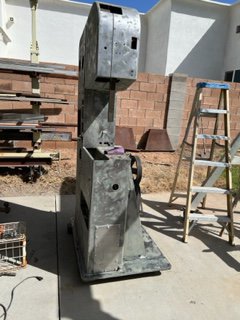
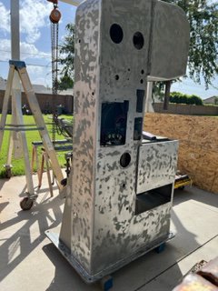
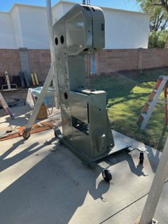
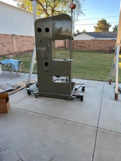
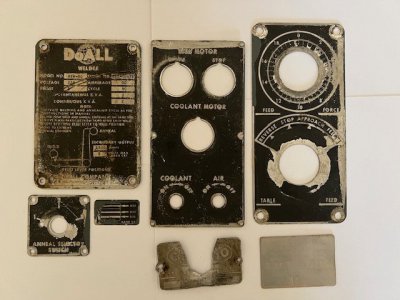
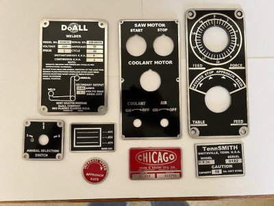
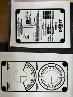
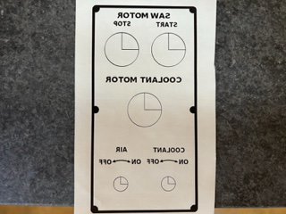
I recently purchased at an auction a 1612-3 with the hydraulic power feed, I attached temporary power just to check the operation of the various components.
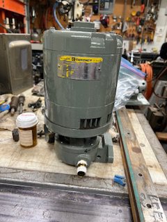
1. Coolant pump is seized but al least the windings check out to be good.
2. the main drive motor runs, I'll be installing new bearings.
3. the transmission shifts into all 3 gears
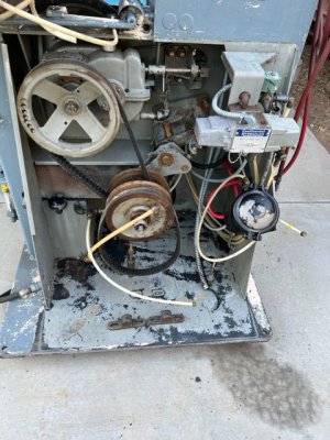
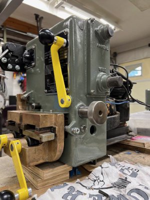
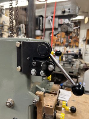
4. variable speed system operates smoothly
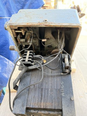
5. The hydraulic pump belt was missing, fluid tank is empty and there is a broken hose on the table hydraulic cylinder.
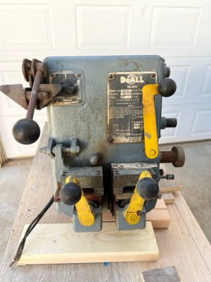
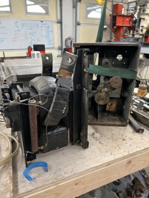
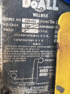
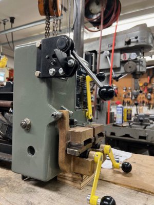
6. did not check the blade welder at this time
7. new grinder motor was installed.
8. the tension gauge and speed meter both work
9. The air pump is missing

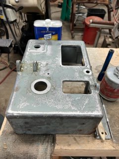
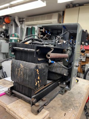
1st issue was that the coolant pump seal failed and sprayed coolant everywhere, mix this sticky substance with decades of metal shaving and you have an indescribable mess. I first tried Spray 9 but it would not touch or dislodge even with the followup of a 3000 PSI pressure washer. I then tried zep purple degreaser, and this only worked when left in the undiluted state. So after 3 gallons of Zep and 1 gallon of spray 9, hours of pressure washing, scraping and wire brushing the saw and the motors (internal and external) are finally free of this sticky mess.

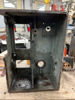
Upon inspection after cleaning
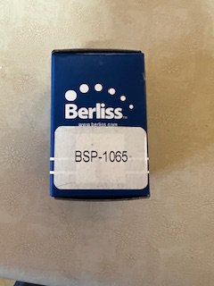
1 coolant pump bearings and seal needs to be replaced, the pump bearings were inexpensive at $15.00 but the 3/8 seal is somewhat pricey from doall. I measured the seal and found that a USSEAL #PS-22028 will work in the pump but the distributor in Phoenix wants almost double the doall price.
2. The saw motor bearings were in good condition, I thoroughly cleaned and re-greased.
3. The wheels could use new tires, this saw uses steel bands that the rubber is glued to and the bands are slipped onto the wheels.
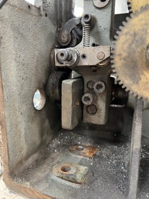
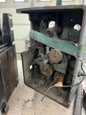
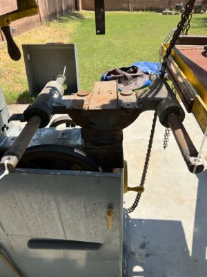
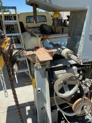
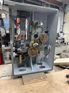
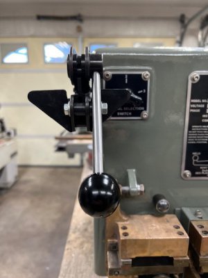
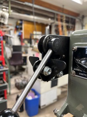
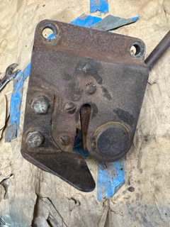
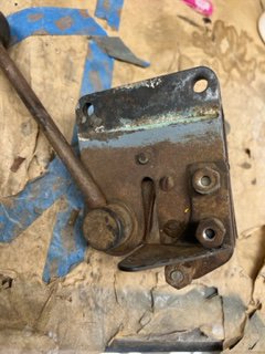
4. The unknown component is the hydraulics, the pump turns but I have yet to disassemble to inspect, I may try to run it with fluid and see what happens and if it works and does not leak I may leave as is. the hydraulic controls and table actuator are also an unknown but I don't see evidence of leaks so hopefully it will all be functional.

I did find a parts manual on the web and the welder operation and parts manual at the doall site. I'm still missing the operations manual for this specific machine and cannot find it on the doall site, I'll call them tomorrow and see if they have one available.

Future plans
1. complete strip and repaint of the exterior frame
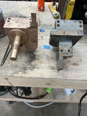
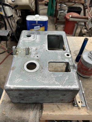
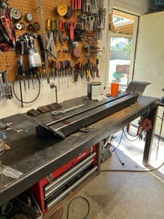
2 Service blade welder, currently have it removed from saw
3. attempt to install new rubber on the wheel bands.
4. Get the hydraulic system fully operational.

Questions for Doall owners
Can anyone tell me what pressure the hydraulics operate at?


Thanks

Greg T
 

Attachments

  • IMG_3656.jpg
    IMG_3656.jpg
    73.5 KB · Views: 30
  • IMG_3681.jpg
    IMG_3681.jpg
    85.1 KB · Views: 30
  • IMG_3672.jpg
    IMG_3672.jpg
    72.5 KB · Views: 24
  • IMG_3673.jpg
    IMG_3673.jpg
    59.6 KB · Views: 29
Nice saw. My old Doall is nowhere as fancy as yours.
 
Sweet saw man! Wish I could help on the hydraulics but my ML doesn't have it. Look forward to seeing this come along. Good luck! :eagerness:
 
Very nice. Mine has the old foot pedal and chain feed.
Martin
 
Hello and thank you for the complements on the saw, it will be a massive upgrade from the Powermatic 143 that I've used for the last 40 years.

I called Doall, they provided me the correct operations manual and did some research and told me that the hydraulic system operates at 200 psi with the 3 gpm pump that is on my saw. My other question to them related to the type / grade of hydraulic fluid, the parts manual is very specific on the oil type and I could not find an alternative to the oil sold by Doall. The service department told me that Mobil DTE 25 would be just fine and there was no need to use the Doall fluid.

I have to say the people at Doall are very helpful and respond immediately to questions. very refreshing and a pleasant a experience.

I ordered a pump seal, but unfortunately its on back-order and I probably will not receive it until mid august.

The saw utilizes .375 od x .048 wall nylon tubing for the hydraulic pressure lines, I found 50' of Parker NNR 6-48 rated at 435 Psi at ebay for a reasonable cost. This gives me plenty of hose for future repairs even after replacing the broken and damaged hoses on the table hydraulic cylinder.

The blade welder had to be removed from the saw frame prior to refinishing the saw, so I moved on to disassembling the the welder and repairing the damaged parts.

Built a cart to roll under the welder to help with removal, then separated the transformer from the welder.

Removed the gear motor and gear train assembly, these and the switch assembly were washed in 99.9%
isopropyl alcohol.

Removed the stationary and moveable blade holder / clamps, much to my surprise after cleaning they are solid copper castings. I don't think that I'm going to repaint them, just leave natural to tarnish unless someone here can give me a reason to repaint.

Used a knotted wire wheel and paint stripper to clean the four layers of paint from the housing.

Almost ready for epoxy primer and paint on the housing and switch plate.

Seeing that I did not have a lot going on this holiday, retired last year and every day is Saturday to me I removed the table to get access to the linear guides.


Attachments

  • IMG_3728.jpg
    IMG_3728.jpg
    219.7 KB · Views: 7
  • IMG_3727.jpg
    IMG_3727.jpg
    316.1 KB · Views: 6
  • IMG_3701.jpg
    IMG_3701.jpg
    378.1 KB · Views: 6
  • IMG_3698.jpg
    IMG_3698.jpg
    304.5 KB · Views: 6
  • IMG_3696.jpg
    IMG_3696.jpg
    329.8 KB · Views: 6
  • IMG_3683.jpg
    IMG_3683.jpg
    357.3 KB · Views: 6
  • IMG_3673.jpg
    IMG_3673.jpg
    270.5 KB · Views: 6
  • IMG_3672.jpg
    IMG_3672.jpg
    337.1 KB · Views: 7
  • IMG_3670.jpg
    IMG_3670.jpg
    334.9 KB · Views: 7
  • IMG_3648.jpg
    IMG_3648.jpg
    440.8 KB · Views: 7
  • IMG_3725.jpg
    IMG_3725.jpg
    330.7 KB · Views: 9
  • IMG_3646.jpg
    IMG_3646.jpg
    107.8 KB · Views: 8
  • IMG_3734.jpg
    IMG_3734.jpg
    73.5 KB · Views: 8
  • IMG_3735.jpg
    IMG_3735.jpg
    73.2 KB · Views: 7
  • IMG_3736.jpg
    IMG_3736.jpg
    68.9 KB · Views: 7
  • IMG_3737.jpg
    IMG_3737.jpg
    77.8 KB · Views: 8
Hello,

It's been a while since I updated, but it was a brutally hot summer in Phoenix so the outdoor work slowed down as painting was not feasible.

The pump seal arrived, fortunately the supplier left it in its original box so the original manufacturer is identifiable. the seal is a Berliss BSP-1065, the only difference between this seal and the original is that the stationary ceramic seat utilizes a perimeter elastomeric on the OD of the ceramic where as the original utilizes a full elastomeric cup. So as long as the seat bore is in good shape this seal should work fine and it's half the cost of the saw manufacturers part plus it's available on Amazon.

During the disassembly of the saw I found that the saw feed blade calculator base sheet metal stamping was left unmolested "not covered in 3 layers of latex paint". This stamping is mostly covered by the calculator so the color was in very good shape, I had this part color matched by English Color in Phoenix and mixed in PPG Essential urethane. Following the installation of the new pump motor bearings I grit blasted the motor housing, stripped the paint from the pump housing in a 5 gal bucket of hot water and Lye "red devil from Walmart" very effective as it dissolves everything down to the base metal with a simple wipe down under clear water. Spray painted the pump motor and pump housing with epoxy primer and followed up with the matched Doall Grey and then reassembled the pump.

I stripped the multiple layers of latex from the saw housing using Norton clean and strip disks on my 7" side grinder and then followed up with 3M Cubitron discs starting with 80 grit and finalized with 220 to blend in any of the original remaining primer. The housing was the sprayed with epoxy primer and color coated in Doall grey.

Following the painting of the saw housing, I need a way to move the saw out of the weather so I sat down and designed a bolt together rolling saw base that utilizes 3x3x.187 HR steel tube and 700 Lb rated 6" casters with swivel locks. I made the caster offsets with 4"x.375 Hr flat stock and bent them in my pressbreak with a 3" die opening and tig welded the main components and bolted the cross tube in with 3/8 Nc bolts.

Next I went back to work on the blade welder, It was completly disassembled and the housing exterior was stripped primed and painted while I only primed the interior. The phenolic ball handles were pretty beat up so I mounted them in the lathe an sanded them through mutiple grits anf then pollished them on the buffer.
I then finished up by making some polished knob offsets out of aluminum.

The blade shear was in pretty bad shape from being out in the weather, so I disassembled and wire brushed the individual components and then used Oxpho cold blueing compound to recolor the parts, it came out surprisingly nice.

Woops looks like I maxed out the photos, I'll follow up on a second post....
 

Attachments

  • IMG_3835.jpg
    IMG_3835.jpg
    17.5 KB · Views: 4
  • IMG_3683.jpg
    IMG_3683.jpg
    23.3 KB · Views: 4
  • IMG_3725.jpg
    IMG_3725.jpg
    22 KB · Views: 3
  • IMG_3723.jpg
    IMG_3723.jpg
    20.9 KB · Views: 3
  • IMG_3846.jpg
    IMG_3846.jpg
    22.5 KB · Views: 3
  • IMG_3863.jpg
    IMG_3863.jpg
    77.1 KB · Views: 3
  • IMG_3864.jpg
    IMG_3864.jpg
    74.7 KB · Views: 3
  • IMG_3865.jpg
    IMG_3865.jpg
    78.4 KB · Views: 3
  • IMG_3866.jpg
    IMG_3866.jpg
    80.7 KB · Views: 4
  • IMG_3834.jpg
    IMG_3834.jpg
    20.5 KB · Views: 4
  • IMG_3830.jpg
    IMG_3830.jpg
    25.1 KB · Views: 4
  • IMG_3867.jpg
    IMG_3867.jpg
    25 KB · Views: 4
  • IMG_3837.jpg
    IMG_3837.jpg
    14.5 KB · Views: 4
  • IMG_3810.jpg
    IMG_3810.jpg
    24.3 KB · Views: 4
  • IMG_3811.jpg
    IMG_3811.jpg
    22.6 KB · Views: 4
  • IMG_3815.jpg
    IMG_3815.jpg
    24.4 KB · Views: 3
  • IMG_3840.jpg
    IMG_3840.jpg
    18.8 KB · Views: 3
  • IMG_3845.jpg
    IMG_3845.jpg
    19 KB · Views: 3
  • IMG_3868.jpg
    IMG_3868.jpg
    28.9 KB · Views: 3
  • IMG_3829.jpg
    IMG_3829.jpg
    27.7 KB · Views: 4
As a follow up to my previous post:

I recolored the the blade shear with Oxpho blue from brownells and it worked surprising well.

And lastly until I start on the saw reassembly and the hydraulic system checkout, I needed to learn on how to recreate the saw data tags as they were in very bad shape.

I honestly have probably spent more time on this than any other aspect of the saw reconditioning project, just one frustrating failure after another. But it's a Phoenix summer 116 deg outside so might as well plant myself in a chair and get started.

For the saw I have a total of 6 data tags, "Saw and pump start, fluid and air control" , "Hydraulic table feed control" , " Hydraulic table speed control" , "Saw Band size" , "Blade welder anneal switch" , "Blade welder position diagram".

And seeing that Im appearently a glutton for punishment I added new data tags for my Chicago D&K sheet metal break and yet to be rebuilt Tennsmith shear.

I started off knowing that I was going to use the laser toner transfer method as I have an older HP 4200. I would also photo editing and vector drawing software, so I installed Gimp and Inkscape which are both free open source. I later discovered that I really didn't need Gimp, but the Gimp controls work very similar to inkscape so it was good to learn. I also later discovered that I needed Libre office draw as Inkscape print did not work for me and Libre office draw navitely imports the inkscape SVG file format.

I started my adventure by first using my iphone camera to photograph each tag and then import to gimp. but without building a fixture to hold the iphone exactly 90 deg to the photo I was never able to correct the skew or scale. I next tried having them scanned to scale at alpha graphics and then importing the pdf to inkscape.

Once imported I created a new layer over the top of the imported file and attempted to trace over the underlaid file, while partialy successful it was just too tedious or I was not skilled enough to utilize the editing tools. I also attempted to convert the imported PDF to a SVG and then use the trace function, but ultimately this also failed becaue of the poor quality scan and the editing was just to tedious.

I finally resorted to using drafting software and a pair of calipers to measure line widths, text height and placement. The file was then saved as a pdf and imported to inkscape. The Pdf was converted to a SVG and I used the Trace function which did not need any editing.

The traced SVG was saved, I then opened a copy and inverted the colors and the image, these were both single click operations in inkscape. I saved the inverted image and opened the document in Libre draw.

The next problem was to find a paper to use as the transfer medium. I tried glossy magazine paper, several types and gloss levels and all were a failure. I also tried some laser transfer for circuit boards that I had but this also failed.

I saw a post on another site that suggested the backing paper from Avery labels, I first tried the backing paper from file labels, but this failed because the paper is to thin. I then tried the paper behind shipping labels, It's thicker and works perfect.

The next problem was getting the toner dark enough, the printer was already configured for the darkest mode. The installed cartridge was an aftermarket refilled so I ordered a new HP cartridge from ebay and this helped but it was still not dark enough.

The solution turned out to be:
1. Print the image on normal bond paper using the letter tray with the back tray open , and make any image location changes with Libre draw.
2. Place a 8.5 x 11 card stock in the letter feed tray and align with the left hand paper stops, print.
3. Cut a retangle/square of avery backing paper and place this glossy side up over the image printed on the card stock.
4. Cut the avery shipping lables into strips and use them to paste down the avery label to the card stock.
5. Carefully align the cardstock into the letter feeder lefthand and top stop and print. Do this 3 times and you have an exceedingly dark laser transfer.

The next problem was the transfer of the image to the .080 5052 aluminum and getting it to adhere good enough to survive the copper sulfate solution etching procedure.

This is what worked for me:
I had two pieces of 1" cast aluminum tool plate, one was used as the bottom plate in the hydraulic press. for the other I screwed a rib to the back so that it could be installed in the upper die holder of the pressbreak.
I cut an oversized piece of aluminum and prepared it by lightly sanding it with 120 grit in one direction and then de-greasing.
This plate is laid face up on the bottom cast tool plate, the image paper is turned face down on the sanded aluminum plate and a blank card stock cut to the appropriate size is placed on top of the image paper.
I heated the top cast plate on the gas stove top to as hot as I could get it, this was then placed in the upper die holder and then brought down on the paper stack for 3 min at 3 tons and then released.
The card stock will turn brown from the heat, carefully remove the card stock as it usually sticks to some degree.
Take the aluminum plate with the transfer paper attached to the top and slip it into a tray of water and let it soak for a few minutes and then gently peal the paper away from the aluminum leaving you a nice dark laser toner transfer thats ready for copper sulfate etching.

Sorry for long winded explanation:
 

Attachments

  • IMG_3871.jpg
    IMG_3871.jpg
    61.6 KB · Views: 2
  • IMG_3870.jpg
    IMG_3870.jpg
    45.6 KB · Views: 2
  • IMG_3869.jpg
    IMG_3869.jpg
    55.9 KB · Views: 2
  • IMG_3827.jpg
    IMG_3827.jpg
    22 KB · Views: 2
  • IMG_3826.jpg
    IMG_3826.jpg
    21.6 KB · Views: 2
  • IMG_3856.jpg
    IMG_3856.jpg
    68.3 KB · Views: 2
  • IMG_3858.jpg
    IMG_3858.jpg
    72.3 KB · Views: 2
  • IMG_3779.jpg
    IMG_3779.jpg
    22.2 KB · Views: 2
  • IMG_3780.jpg
    IMG_3780.jpg
    18 KB · Views: 2
  • IMG_3781.jpg
    IMG_3781.jpg
    19.5 KB · Views: 2
  • IMG_3782.jpg
    IMG_3782.jpg
    19.1 KB · Views: 2
  • IMG_3786.jpg
    IMG_3786.jpg
    20.4 KB · Views: 2
  • IMG_3789.jpg
    IMG_3789.jpg
    16.1 KB · Views: 2
Last edited:
Back
Top