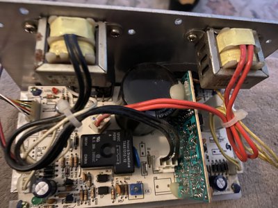
DC treadmill motor wiring info needed

The KBLC 19 PM has a 12 amp rating with additional heat sink . While I can find heat sinks in salvage,nothing says where to attach it.
you bolt the flat side of the aluminum chassis plate the controller is on to the heat sink. KB says that a sink with a width of 7 to 8 inches, height of 6-8 inches, and fins 7/8" to 1" tall on 3/8" centers will fit the bill. You want a sink with a flat back for mating to the flat side of the aluminum chassis plate. Be sure and get a thin coat of heat sink goo (that's a technical term, BTW :) ) between the two flat metal surfaces. KB electronics has a a manual for their controllers that shows much of this.

In operation, the fins must be oriented vertically, so chimney effect flows air up through them.

Appreciate the info .I must keep missing some info in the manual I downloaded by not know exactly what to look for. I ordered the resistor and will try and find the size for the speed pot. . Will be keeping an eye out for said heat sink item and look for some goo the next time I'm at the electronics store. Probably the same stuff I've used when attaching processors to the computer boards I've assembled in the past. I guess it's a conductive grease of sorts but I like goo description better.
Also noted several hookups for switching but initially will only be doing one direction since these motors are one direction only for fan cooling.May later be able to find a bidirectional motor for lathe . Would be nice to have speed control on it without gear changing.
 
Will be keeping an eye out for said heat sink item
This is a good one, although it's long enough to get two of them out of it: http://www.ebay.com/itm/Aluminum-He...567?pt=LH_DefaultDomain_0&hash=item519e4beb67

Here's another:
http://www.ebay.com/itm/Aluminum-He...297?pt=LH_DefaultDomain_0&hash=item56494f6099

Here's another:
http://www.ebay.com/itm/Aluminum-He...651?pt=LH_DefaultDomain_0&hash=item416400beab

You get the idea: about 6-8" wide, more than 7-8" long, fins 1" or so high, and a flat back to bolt the controller to.
and look for some goo the next time I'm at the electronics store. Probably the same stuff I've used when attaching processors to the computer boards I've assembled in the past. I guess it's a conductive grease of sorts but I like goo description better.
The computer store stuff will do, but it's expensive for what it does. They went hifi tweako on that stuff. Ordinary white heat sink goo is fine for this. The goo is just filling in the air pockets from the imperfect surfaces of the carrier and sink not mating well. Air is a great insulator, so almost anything in the voids will work better than air. Likewise, you want any machining/screw holes, etc. to not have made a raised bump to keep the flat surfaces apart. What you're after is as nearly 100% metal-to-metal surfaces as you can get. Space stuff laps the surfaces together.

Also noted several hookups for switching but initially will only be doing one direction since these motors are one direction only for fan cooling.May later be able to find a bidirectional motor for lathe . Would be nice to have speed control on it without gear changing.
DC motors also have a preferred direction and the brushes are slanted to make that work best. They can be reversed, but you get much more brush wear.

I just removed a motor from a throwaway treadmill for my drill press. :)
 
Jericho
I just joined and I have the exact treadmill motor and controller you are showing in the pictures and mine also came without the opperator panel. Did you ever get yours to work? I saw where you got the KB controller which I may have to do but it also sounded like you were going to be trying to figure out thr board that came with the motor.
Thanks,
Kirk
 
Kirk: apologies for not being on site in a while.Just now reading message.I in fact did get the KBIC controller and it worked so well I gave up on the other.With no background in electronics I was still at a loss to fix.In fact I now have KBIC controllers for all three DC motors I scrounged at the scrapyard.

Jericho
I just joined and I have the exact treadmill motor and controller you are showing in the pictures and mine also came without the opperator panel. Did you ever get yours to work? I saw where you got the KB controller which I may have to do but it also sounded like you were going to be trying to figure out the board that came with the motor.
Thanks,
Kirk
 
Hahaha I KNOW this is a zombie thread! But in case anyone else comes across it while they're looking to hook up they're treadmill motor on Board fh-3545c-pw-n :
-The red wire is the power to the control board.
-Connect it to the Blue wire, and you'll here a click (that's the relay turning on).
-Then connect the Red wire (still connected to the Blue wire) to the high side of a pot (set up as a variable resistor).
-Connect the Green wire to the wiper
-You're GTG
I've found a 25K Pot works, and 5K does not (too little resistance I guess). Might be a better Value in between, but I'm a hammer and chisel mechanic. It'll do for the purposes I have in mind.

Now to see if there's a resistor I can clip so the pot doesn't have to be reset everytime this gets turned on.

* I do not vouch for the long term reliability of these connections. It's been working for 10 minutes at a slow speed.
Nothing's hot. It'll get you up and running at least. this is decent motor.
 
follow up. There's a place for a jumper that reads "Option" right in front of the pin header.
If you jumper that, you don't need to reset the pot everytime you turn it off then on again :encourage:
 
Hahaha I KNOW this is a zombie thread! But in case anyone else comes across it while they're looking to hook up they're treadmill motor on Board fh-3545c-pw-n :
-The red wire is the power to the control board.
-Connect it to the Blue wire, and you'll here a click (that's the relay turning on).
-Then connect the Red wire (still connected to the Blue wire) to the high side of a pot (set up as a variable resistor).
-Connect the Green wire to the wiper
-You're GTG
I've found a 25K Pot works, and 5K does not (too little resistance I guess). Might be a better Value in between, but I'm a hammer and chisel mechanic. It'll do for the purposes I have in mind.

Now to see if there's a resistor I can clip so the pot doesn't have to be reset everytime this gets turned on.

* I do not vouch for the long term reliability of these connections. It's been working for 10 minutes at a slow speed.
Nothing's hot. It'll get you up and running at least. this is decent motor.
I joined mostly to thank JRock1000 for all the info! That really helped me out. Mine came with differently colored wires for the cable between motor controller and the control panel. I was short on time when I picked up my motor and motor controller. I wasn't able to get the control panel or record the make/model of the treadmill I was pulling parts from. My speed control board is FH-3545C-PW-N VER:E1 and my motor is ACA400-12091. (The speed control pictured in the OP is VER:B1) The wires on my cable were colored differently vs what Jericho or JRock1000 had. Connector P1 colors starting with Pin 1: purple, brown, red, black, orange, yellow, blue green. The function of the pins seems to be the same, but the colors threw me off at first! Connector P1 on both boards is an 8 pin socket on a 10 pin PCB footprint.

Pin 3: Provides a positive DC voltage to several other pins.
Pin 7: Connect this to Pin 3 in order to close the relay. This is required to operate the motor.
Pin 5: Connect to Pin 3 using a variable resistor

The above is exactly as described by JRock1000, just referenced using pins instead of colors. My DC supply voltage for the control panel was a little lower (more like 16v). What I had on hand was a 10k pot and a 100k pot. Like JRock1000, I found that the 10K pot just wouldn't quite do it. With the 100k pot it seemed like the minimum speed is somewhere around 43k and the maximum speed is roughly 25k. (Testing with the motor disconnected just now, 25k through 0k gives the same output voltage.)

VER:E1 also seemed to be wired for a optical speed sensor instead of magnetic. I just cut the cable, but I saw the slotted wheel and it's a 3 conductor cable now instead of 2 conductor.
 
Last edited:
Jerico,
I'm taklking about the origional controller. I have "Freecycled" several treadmills. Got real lucky with 2, they had the famous MC-60 controller.
Most tread mill controllers have a 3 wire connection to a speed control pot. AC input, and DC out to the motor. I have an MC-60 controller and 2.5 hp motor running my X2 mill at the moment. Still in a "cobbled together to try it" state, but functional. So far, I like it and am considering spiffing it up a bit and making it permanent.
I'm near Kingsport, just off I81. I am on spring break next week, but have company until Thursday. Plus, I'm retiring in May, so will have time to assist if you need it.

Chuck
Guys, I know a lot of Time has passed since this post but hoping y’all ar still breathing air. I picked this old FH-3545c-pwn ver. B1 at garage sale. I have a dc motor running both my wood lathes and thinking about putting this little girl to work doing something but I can’t figure out where power comes into it and about the pot. The picture may not be clear, if not I might could get a close up view. Anyone know about this baby. I tell you there are more treadmill controller models out there than love bugs in Louisiana.
Thanks y’all
zetuskid4AD34FAE-30A5-41AC-8FA8-45780B514C61.jpeg
 
Back
Top